
Design points of injection mold for color double-sided printer shell
Time:2022-09-05 08:20:53 / Popularity: / Source:
Product diagram of color double-sided printer enclosure is shown in Figure 1. Maximum external dimensions of product are 350.10 mm * 292.30 mm * 236.90 mm, average thickness of plastic parts is 2.50 mm, material of plastic parts is HIPS, shrinkage rate is 1.005, and weight of plastic parts is 452.6 grams. Technical requirements for plastic parts are that there shall be no defects such as peaks, underfilling of injection molding, flow lines, pores, warpage deformation, silver lines, cold materials, and spray lines.

Figure 1 Product picture of color duplex printer shell
As can be seen from Figure 1, size of plastic part is large, and slider core needs to be designed on all four sides. Therefore, mold design cavity ranking can only use 1 cavity. Mold is a large mold, and mold base is a non-standard mold base 9095. For such large plastic parts, gating system can only use a three-plate mold or a hot runner system. Because plastic parts are large and there are many gates, three-plate mold with narrow nozzle is convenient to design multiple point gates. Gating system is designed with 6 gates. One side of plastic part is designed with 2 small gates to turn side gates, and the other side is designed with 4 fine gates to latent gates.
As can be seen from Figure 1, size of plastic part is large, and slider core needs to be designed on all four sides. Therefore, mold design cavity ranking can only use 1 cavity. Mold is a large mold, and mold base is a non-standard mold base 9095. For such large plastic parts, gating system can only use a three-plate mold or a hot runner system. Because plastic parts are large and there are many gates, three-plate mold with narrow nozzle is convenient to design multiple point gates. Gating system is designed with 6 gates. One side of plastic part is designed with 2 small gates to turn side gates, and the other side is designed with 4 fine gates to latent gates.
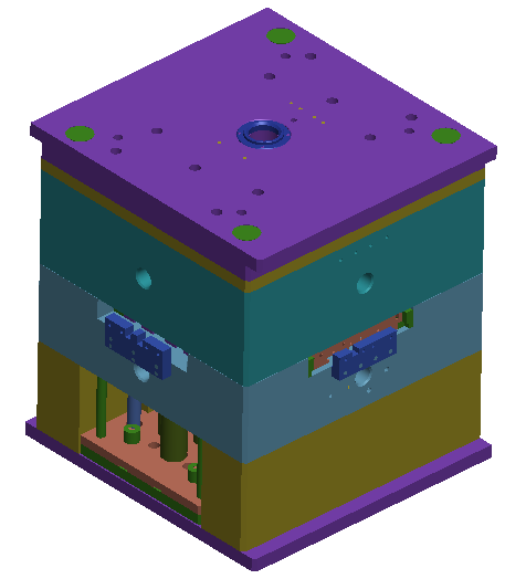
Figure 2 Color duplex printer shell mold diagram
Three sides of plastic part are closed structural shells, and top surface is a sunken curved surface, which is paper-through surface through which paper passes. There are two upside-down buckles on paper surface, and fixed die slider needs to be designed. Movement of two sliders on paper surface can only be moved inward and opposite to core by two inverted sliders. It is not possible to design a slider to move outwards, because bottom surface here is a curved surface, and sliders cannot move outwards.
Five sliders on four sides of plastic part are all rear mold sliders. Due to high height of plastic part, corresponding slider height is also high. Sliders are all driven by inclined guide columns, and bottom of sliders is guided by T-shaped grooves, as shown in Figure 4. Wear plates of rear die sliders are all designed on slope of sliders, and the whole wedge is opened on A plate, which has a strong mold locking force, which can effectively resist lateral separation force of five sliders. Because slider is very high, inclined guide column must be designed at lower part of tail of slider to make slider move smoothly. Three large sliders are very wide, and three inclined guide columns are designed respectively. Installation of inclined guide columns adopts a fixed block to extend wedge, and after pressing slider, it acts as a backhoe. This installation scheme has a simple structure and is convenient for mold processing. Positioning of slider adopts out-of-mold spring positioning. If spring is designed at the front end of slider, failure of spring is not easy to detect, and it is easy to cause an injection accident.
For processing of large sliders, since top surface of plastic part is a curved surface, parting surface of side large slider is horizontally extended from tangent point of R angle between side and top surface of plastic part. Top surface of slider must be designed as a plane as processing reference surface, as shown in Figure 4.
Two front die sliders on paper surface are symmetrically designed and driven by a T-slot wedge. In the case of limited space, front die slider is generally driven by a T-slot wedge.
Paper surface of office machinery such as printers and copiers is a very important surface. In order to reduce friction between paper and paper surface, some arc bones are generally designed on paper surface. These bones need to be smooth and consistent. All through-paper surfaces must be flat and smooth, free of various injection molding defects, gate marks, clamping lines caused by slider inserts, and ejection marks.

Figure 3 Design of slider and parting surface

Figure 4 Slider Design
Outer surface treatment of printer casing usually adopts a combination of etching texture, matte texture and local highlight. Surface treatment area is usually marked on product map of plastic part. Etched steel has higher requirements and cannot be easily welded. For important molds, an etching effect test should be done. Avoid differences in appearance of various areas after mold is etched.
Ejection of plastic parts adopts 4 lifters and ejector pins.
Cooling system of mold adopts front mold to directly transport water, and rear mold is cooled by a pool. Large slider also adopts straight-through water transportation, which effectively improves cooling efficiency.
In terms of mold structure, for large molds, if a three-plate mold is designed, it is not enough to rely on nylon buckles when opening mold. A spring must be added between runner push plate and A plate to assist in opening mold to ensure that runner condensate is in the first place. It was pulled off during second parting.

Figure 5 Design of rear mold core and lifter
Recommended
Related
- Motor Support Plate Die-Casting Process Design and Optimization07-29
- A Comprehensive Guide to Hot Runner Thermostats in Injection Molds: How Experts Choose, Use, and Rep07-29
- Hydraulic Cylinder Core Pulling Design Considerations07-28
- Interpreting Four Key Parameters of Injection Molding and Their Impact on Product Quality07-28
- Taking silicone oil fan clutch housing as an example, let's discuss analytical logic of leakage07-27