
What factors are affecting your injection molding cycle time? (3)
Time:2022-09-03 09:03:31 / Popularity: / Source:
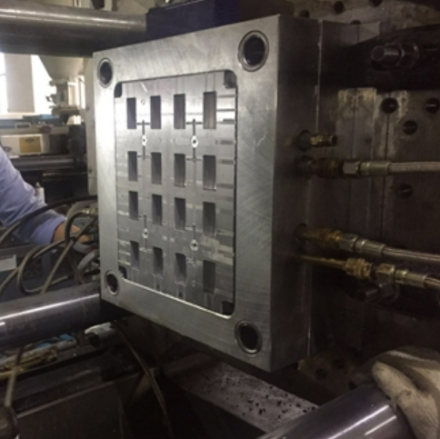
Recently, we received a video from a client who sent us. This is a simple set of cold runner molds with a circular runner and a cold slug well, and cavity is also small. My original suggestion was to replace cold gate with a hot-to-cold runner to help reduce cycle time and save material, but this suggestion was not taken.
Second thing I noticed was that mold was about 12 inches open. The longest part of product is only 3 inches. From this point of view, mold opening stroke can be reduced by at least two-thirds, leaving about 4 to 5 inches of distance. This measure saves about 1 second of cycle time. Current cycle is 15 seconds, so just setting proper mold opening stroke equates to a profit increase of about 7%.
Second thing I noticed was that mold was about 12 inches open. The longest part of product is only 3 inches. From this point of view, mold opening stroke can be reduced by at least two-thirds, leaving about 4 to 5 inches of distance. This measure saves about 1 second of cycle time. Current cycle is 15 seconds, so just setting proper mold opening stroke equates to a profit increase of about 7%.

Setting correct ejection stroke reduces cycle time
Another concern is ejection stroke of ejector pin. Parts fall freely after being ejected by ejector pins. Some technicians habitually like to add extra ejection strokes to ensure that parts can be ejected and increase insurance factor. Unless product is very long, thin or fragile, way to increase insurance factor is to properly set low pressure containment of mold, rather than adding extra ejector stroke, such a setting will wear out ejector system and ejector pin holes faster .

Insufficient ejector stroke
Insufficient ejection stroke of machine is an occasional problem, that is, maximum ejection stroke that machine can provide is not enough to eject product smoothly. This problem should be confirmed before mold is installed on injection molding machine. In general there are two possible solutions. The first is to replace injection molding machine with a larger ejector stroke, but doing so will increase part costs and reduce profits. Second method is to install special devices that can additionally increase mold opening stroke.
There are many devices that do this, including old-fashioned roller chains, unstretched timing belt chains shown in Figure 1, standard Range bolts shown in Figure 2, Range Bars shown in Figure 3, telescoping shown in Figure 4 range bars and hydraulic cylinders as shown in Figure 5.
There are many devices that do this, including old-fashioned roller chains, unstretched timing belt chains shown in Figure 1, standard Range bolts shown in Figure 2, Range Bars shown in Figure 3, telescoping shown in Figure 4 range bars and hydraulic cylinders as shown in Figure 5.

Figure 1 Timing belt chain without tension

Figure 2 Standard Range bolts

Figure 3 Range Bars

Figure 4 telescoping range bars

Figure 5 Hydraulic cylinder
Except for hydraulic cylinders, all other methods mentioned are pulling devices. They are limited to one forward ejection stroke and require a return pin to push ejector plate back into place. Hydraulic cylinder can be ejected as many times as needed.
Except for hydraulic cylinders, all other methods mentioned are pulling devices. They are limited to one forward ejection stroke and require a return pin to push ejector plate back into place. Hydraulic cylinder can be ejected as many times as needed.
Validate ejector stroke of machine during design phase
Parts stick to mold
Parts sticking to ejector pins or other mold components during mold sampling are often caused by mold design errors. Part sticking is often caused by mold wear after thousands of hours of production. In general, mold design errors are more common cause of part sticking.
Parts sticking to ejector pins or other mold components during mold sampling are often caused by mold design errors. Part sticking is often caused by mold wear after thousands of hours of production. In general, mold design errors are more common cause of part sticking.
Parts can stick to ejector pins for various reasons, especially if ejector pins are in the corners. Figure 6 shows worst case, where thimble is not only at the corner, but also at a 90° right angle. Shrinkage is often root cause of parts sticking to ejector pins. Most mold designers will design ejector pin position in the corner of product, thinking that this is place where part and mold make the tightest contact, which is completely correct. But these locations are also generally the hottest places in die steel. Therefore, it is necessary to design cooling water pipeline to corner of core, and place thimble next to cooling water pipeline.

Figure 6 Thimble at the corner of part
It is also common for parts to stick to thimble when thimble is slightly embedded in part. Ejector pin may be too long or ejected too early, pushing ejector pin slightly into part. A simple solution is to make sure ejector pin is flush with or slightly below part surface and use a larger diameter ejector pin.
However, sometimes longer thimbles are intentionally used. In this case, placing thimble into bushing or barrel so that desired amount of protrusion will help prevent part from sticking to the thimble, as shown in Figure 7.

Figure 7 Cylinder needle
Another reason for parts sticking to mold is that two ejectors cannot keep pace. When ejector pins are ejected, part may stick to one of ejector pins. The best solution for this situation is to use a two-stage ejector system with two ejectors. Of course, if molds have already been opened, investment in adding a two-stage ejector system will be higher.
A less expensive solution is to add a pointed or bull-headed ejector bar to keep part ejected during ejection, as shown in Figure 8. If mold is side gated, you can add an ejector pin on gate, as close to gate as possible.

Figure 8 Bull-nosed ejector pin.
Another simple and effective trick is to use a "delayed back" with one or two jacks. As ejector system is retracted, delayed ejector pins remain slightly forward and push the part away from other ejector pins. FIG. 9 is a schematic diagram.
Another simple and effective trick is to use a "delayed back" with one or two jacks. As ejector system is retracted, delayed ejector pins remain slightly forward and push the part away from other ejector pins. FIG. 9 is a schematic diagram.

Figure 9 Schematic diagram of delayed return design of ejector system
Another reason for parts and runners sticking to ejector pins is use of a "Z-pin" to pull gate out of bushing on A side, as shown in Figure 10. When using this type of ejector pin, it must be oriented so that part and runner can fall freely after ejection.
Another reason for parts and runners sticking to ejector pins is use of a "Z-pin" to pull gate out of bushing on A side, as shown in Figure 10. When using this type of ejector pin, it must be oriented so that part and runner can fall freely after ejection.

Figure 10 Z-shaped design
Mold opening and ejection mechanism have a great impact on injection cycle, and need to be optimized from design stage.
Mold opening and ejection mechanism have a great impact on injection cycle, and need to be optimized from design stage.
Recommended
Related
- Motor Support Plate Die-Casting Process Design and Optimization07-29
- A Comprehensive Guide to Hot Runner Thermostats in Injection Molds: How Experts Choose, Use, and Rep07-29
- Hydraulic Cylinder Core Pulling Design Considerations07-28
- Interpreting Four Key Parameters of Injection Molding and Their Impact on Product Quality07-28
- Taking silicone oil fan clutch housing as an example, let's discuss analytical logic of leakage07-27