
Type characteristics, selection of hot runner nozzles and gates
Time:2019-04-01 11:24:29 / Popularity: / Source:
- Single nozzle and multiple nozzle

Figure 1 needle valve type single nozzle

Figure 2 Single nozzle of main channel gate

Figure 3 needle valve multi-nozzle

Figure 4 needle tip multi-nozzle
- Needle valve type and open nozzle
Figure 3 is a needle valve type multi-nozzle installed under flow path plate. Its valve needle passes through flow passage plate and is driven by a cylinder mounted on fixed mold fixing plate. Variety of plastics for needle valve gates is basically unlimited. Plastic melt has a large pressure drop in the nozzle, and too long valve needle is easily destabilized under melt pressure. Needle valve nozzle is driven by hydraulic oil or compressed air and needs to be connected to operation signal of injection molding machine. For multiple needle valve nozzles, each nozzle can be controlled to open and close according to program, so that fusion joint can be transferred to optimal position. It is also possible to open nozzle at the front of flow to successfully eliminate fusion joint. As shown in Figure 3, needle valve type nozzle is controlled by instrument and cylinder is executed to ensure proper injection pressure keeping time, trace of gate is small, which is used by mold designers. In recent years, there has been a trend of application expansion. Needle valve opening and closing is reliable, but it should be noted that needle valve type nozzle is complicated in structure and expensive.
| Plastic fluidity | Material type | Injection volume/g | |
| Direct gate | Tip gate | ||
| Good | PE/PP/PS | 2000 | 170 |
| Medium | ABS/ASA/PA/PBT/PET/POM/PPO/SAN | 1500 | 120 |
| Worse | PC/PEEK/PEI/PMMA/PPS/PSU | 800 | 60 |
Figure 4 is an open multi-nozzle tip gate for hot runner injection molding mold with two or more nozzles under hot runner plate. Gate is on fixed template, and gate hole is processed by injection moulding suppliers. Nozzle sprue has a flow guiding rod, middle side is provided with beryllium copper with good heat conduction to increase temperature of melt in the center of gate. There are only tiny needle marks on the surface of molded part. There is a cooling water pipe near gate, which is fully cooled. Temperature in gate area is low, suitable for amorphous plastics such as ABS, PS and PMMA, and slow-crystallized plastics such as PE and PP. However, injection amount of nozzle is small, as shown in Table 1.
- Open nozzle gate

Figure 5 side hole multi-nozzle

Figure 6 Improved side hole multi-nozzle
Figure 5 shows an open multi-nozzle side hole gate. There is no sprue sleeve, gate is on fixed template, and gate hole is processed by injection moulding suppliers. Temperature in gate area is low and there are only tiny needle marks on the surface of injection moulded parts. Compared with tip-type gate shown in FIG. 4, plastic melt is rushed from flow passage through 2 to 3 holes in cone tip, and pressure loss through gate is small. Moreover, a heat insulating skin layer can be formed on inner wall of gate hole of taper tip. Therefore, temperature and allowable injection amount of gate area are higher than that of needle tip gate, and it is suitable for plastics such as ABS, PMMA, PE and PP which have a lower melt injection temperature.

Figure 7 sprue sleeve tip multi-nozzle
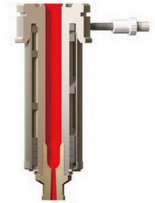
Figure 8 Main nozzle multi-nozzle with sprue bushing
3.2 Nozzle with sprue sleeve
Figure 7 shows open multi-nozzle tip gate. It has a sprue bushing, which is used for thermal insulation. Gate area is warmer. Precision of tip and hole of gate is guaranteed. Injection gate has only tiny needle marks on the surface of injection moulded parts, but will leave a ferrule indentation on the surface of injection moulded parts. Suitable for amorphous plastics such as ABS and PMMA, especially for slow-crystallizing PE and PP plastics. It is easy to install and debug, and has good color change performance.
Figure 8 shows open multi-nozzle sprue. Sprue bushing with inverted cone through hole not only leaves ferrule indentation on the surface of injection moulded parts, but also leaves a conical cold shank on injection moulded parts. If necessary, injection moulded parts needs to be inverted and injection molded, and thermal closing is relatively reliable. However, there may be wire drawing or runny when temperature in gate area is too high. Suitable for most plastic types, especially for high viscosity plastics such as PC and various glass fiber reinforced plastics. It is suitable for large thick-walled deep cavity injection moulded parts, hot runner and cold runner mixing system.
- Hot runner nozzle selection
4.1 Impact of plastic materials
Processing range and thermal properties of plastic must be fully understood in order to accurately and effectively control gate freezing time of hot runner system, which is especially important for choice of gate form. First understand effect of temperature on various plastic forms. Plastic molecular structure is established from cooling solidification, and thermoplastic can be divided into two groups.
One type is plastic with amorphous structure, and microscopic molecules maintain a disordered state in a bonded form. PS, ABS, cellulose acetate CA, polyphenylene ether PPO, PVC, PC, PSU and fluoroplastics are amorphous plastics. In addition to PVC and CA, other materials have a wide processing temperature range. Amorphous plastics also have a high elastic state between solid state and molten liquid state. For example, ABS, melt flow temperature is 180-250℃, semi-flow high elastic temperature is 110-180℃, it has a temperature range of 140℃ injection and holding pressure, viscosity gradually changes during heating and cooling, injection molding shrinkage rate is less than 1%, influence of holding pressure and time is small. In addition to PVC and PC, gate area is allowed to have a lower temperature.
The other type is a crystalline structural plastic in which molecular chains are sequentially folded along formed crystal nucleus, but surrounding is still an amorphous structure, and thus there is a degree of crystallinity. Crystalline plastics include LDPE, HDPE, PA, POM, PET, PBT, and polyphenylene sulfide PPS. Range of temperature fluctuations defining injection holding pressure is narrow, and temperature of flow path plate and nozzle must be strictly controlled. When injection moulded parts is cured, it quickly passes through crystallization temperature. Cooling crystallization requires mold to carry more heat. Mold temperature involves degree of crystallization and quality of product. There is a large injection molding shrinkage rate, and it is necessary to prevent gate from freezing prematurely, so that pressure and time are insufficient. A "warm" gate area that requires a higher temperature.
Crystalline plastics require a higher temperature gate area to ensure plastic shrinkage in cavity. A complete nozzle with a sprue bushing can be applied, as shown in Figures 2, 7 and 8. Gate is made of stainless steel with a high chromium content. This part is called an insulated sprue bushing. Some are made of titanium alloy to reduce heat transfer of cold template to gate.
Most crystalline plastics have a processing temperature range of less than 60℃, of which POM and PA are rapidly crystallized, and processing temperature range is less than 30℃, such as heating temperature of PA66 plastic is 255 to 285℃. A higher temperature is required in gate area than slow-crystallized PE and PP, so that a needle valve nozzle is preferred. In the case of open gates that are thermally closed, it is preferred to have a one-piece nozzle with a sprue bushing.
4.2 Influence of gate marks
Using a direct nozzle as shown in Figures 2 and 8, a tapered columnar residual shank is left on plastic article. This gate trace remains on outer surface of article, residue is tall and must be cut. If it is to be left on inner surface, mold has a flip-chip structure. It is necessary to consider whether demolding mechanism is feasible in fixed mold, and also consider whether it is possible to cut gate handle, possibility of gate drooling and drawing is greatest. Common gates are 2.7 to 10mm in diameter and are suitable for a wide range of plastics. Direct nozzle features minimal pressure drop across gate and is suitable for high viscosity plastics such as PCs. Mixing and pouring system of main channel hot nozzle and cold runner-gate is used to make nozzle have a long distance from product cavity, which is beneficial to increase temperature of gate area.
As shown in Fig. 4 to Fig. 6 side hole type and needle tip type nozzles, common gate diameter is 1 to 3 mm. Central tip has a guide tip to prevent dripping and drawing of melt. Larger diameter gate is conducive to melt flow filling, and can also increase strength of conical tip; Smaller diameter gate leaves less trace on the product, and gate marks are hard to detect.
There is a guide bar in needle tip gate. Injection section is a circular gap, which produces largest shear stress, which will lead to temperature rise and degradation of molecular structure of melt plastic, causing molecular chain breakage. High viscosity plastics such as PC, and modified high viscosity plastics are restricted. Moreover descaling of needle tip nozzle is laborious, and melt is easily retained, making coloring replacement difficult. PVC, POM and flame retardant-containing plastics should not be used.
For nozzles with a sprue bushing, thermal expansion of sprue bushing and stencil in nozzle axis direction is inconsistent, leaving a ring of sprue bushing in injection molded part.
As shown in Figures 1 and 3, needle valve nozzle is used to have no gate residue on injection molded part, but leaves a trace of valve needle on product. Gate diameter is 2 to 8 mm, which is not suitable for a small amount of injection molding of only a few grams.
4.3 Injection volume of nozzle
Viscosity of a wide variety of plastic melts at injection temperatures varies widely. High pressure plastic melts have a large pressure loss when flowing through runners and gates. When using a needle tip or needle valve nozzle, consider a large pressure drop in nozzle flow process. There will be viscous heat in narrow and long flow passages, which will increase temperature of plastic melt, which will cause plastic to degrade and discolor. Low viscosity plastic melts are prone to leakage.
From viscosity of plastic melt, gate type is selected by maximum injection volume of nozzle, as listed in Table 1. Direct gate allows 1 to 2 kg of medium viscosity material and 100 to 200 g of needle tip type. Needle valve gate is somewhere in between.
After selecting gate type, refer to catalogue of hot runner company to preliminarily define type of nozzle. Hot runner nozzle runner diameter and gate structure size are further determined.
Last article:Plastik injection moulding workshop decoration
Next article:10 factors that affect quality of injection moulding
Recommended
Related
- A Complete Guide to Plastic Mold Processing: From Roughing to Mirror Finish, Key Points of Each Step07-30
- Injection Mold On-Site Troubleshooting and Practical Repair Manual07-30
- Motor Support Plate Die-Casting Process Design and Optimization07-29
- A Comprehensive Guide to Hot Runner Thermostats in Injection Molds: How Experts Choose, Use, and Rep07-29
- Hydraulic Cylinder Core Pulling Design Considerations07-28