
What is benefit of using a secondary roll-out forced demoulding instead of side core pulling?
Time:2020-06-30 09:30:10 / Popularity: / Source:
1 Plastic parts analysis

Figure 1 Plastic parts structure
Button is a commonly used electrical control element, used to turn on or off control circuit to achieve purpose of controlling operation of motor or other electrical equipment. Size of button structure is shown in Figure 1. There is an inside undercut structure below it. Height of inside undercut is 0.4mm. Mold demoulding mechanism design for inside underside of button needs to be considered when designing mold. Plastic parts are made of ABS with a shrinkage rate of 0.5%. Buttons are electrical components, which have high requirements on impact strength and external surface. External surface is required to be smooth and free of defects such as pores, flashes, and weld marks. Combined with appearance requirements of plastic parts and selection principle of parting surface, parting surface of plastic part is selected at maximum area of plastic part. As shown in Fig 1A-A, latent gate side feeding method is adopted to ensure quality of outer surface of plastic parts.
2 Mold structure design
01 Design of parting surface and gating system
There is no obvious gate mark on outer surface of button plastic part. In order to ensure appearance quality of plastic parts and facilitate demoulding, latent gate feeding is adopted, and gate is set on the side of plastic parts. According to selection principle of parting surface, parting surface is located at maximum projected area of plastic part, and its position is shown as A-A in FIG. 1. Diameter of small end of main channel is φ2.0mm, and taper is 3 °.02 Structure design for second launch of forced demoulding mechanism
Plastic part is a dome-shaped structure, side wall has a slope of 1 °, and there is a round inside undercut inside plastic part. Conventional design method is to design corresponding side core-pulling mechanism, complete demoulding of undercut before mold is opened to ensure smooth demoulding of plastic part and forming quality of inner circular underpinning, but mold structure of conventional side core-pulling mechanism is complicated, and mold manufacturing cost is high. Aiming at characteristics of plastic underside of plastic parts (horizontal release height of inner backing is 0.5mm, which meets conditions of forced demoulding), secondary round underside of plastic parts is forcedly demolded by second push, which simplifies mold structure and reduces mold manufacturing cost.Second introduction of forced demoulding mechanism is aimed at plastic parts with a certain degree of ductility. Process of demoulding under action of external force is carried out by using elasticity of plastic parts without damaging plastic parts. In order to ensure smooth progress of forced demoulding of circular undercut inside plastic parts, it is necessary to reserve a demoulding space on the outside of circular undercut before forced demolding, so core is inlaid, as shown in Figure 2, core insert 3 and core insert 4 form inner surface of inner round undercut of plastic part, and core 8 forms outer surface of inner round back of plastic part and inner surface of plastic part. Demoulding of plastic parts is completed by four φ5mm push rods located in the center of plastic parts.
03 How mold works
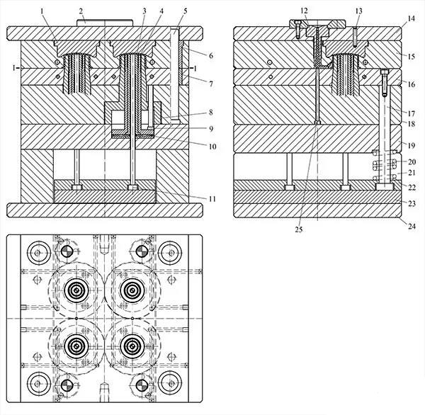
Figure 2 Mold structure
1. Cavity plate 2. Positioning ring 3. Core insert 4. Core insert 5. Guide post 6. Guide sleeve 7. Push plate guide sleeve 8. Core 9. Core reset lever 10. Lock pin 11. Push rod 12. Sprue bush 13. Stop pin 14. Fixed mold seat plate 15. Cavity fixing plate 16. Push plate 17. Limit rod 18. Core fixing plate 19. Support plate 20. Spring 21. Pad 22. Push rod fixing plate 23. Push plate 24. Mould base plate 25. Pull rodAs shown in Fig. 2, after injection, holding and cooling of plastic melt, main parting surfaces Ⅰ-Ⅰ are opened when mold is opened, ejector rod of injection molding machine pushes push plate 23 to move upward, driving push rod 11 to push plastic part out of core 8. And at this time, movable core insert 3 and movable core insert 4 move up with plastic part. As mold-opening stroke progresses, core insert 3 and core insert 4 stop moving upward under limit of core 8, and push rod 11 continues to move upward under action of push plate. Due to its own elastoplasticity and external force, round reverse button inside plastic part springs out to complete forced demolding of round reverse button inside plastic part. Finally, push rod 11 continues to move forward, plastic part is pushed out from core insert 3 and core insert 4 to complete demoulding of plastic parts and mold opening is completed. When mold is closed, return spring drives push plate 16 and core reset rod 9 to reset, completing entire injection molding cycle.
Recommended
Related
- Motor Support Plate Die-Casting Process Design and Optimization07-29
- A Comprehensive Guide to Hot Runner Thermostats in Injection Molds: How Experts Choose, Use, and Rep07-29
- Hydraulic Cylinder Core Pulling Design Considerations07-28
- Interpreting Four Key Parameters of Injection Molding and Their Impact on Product Quality07-28
- Taking silicone oil fan clutch housing as an example, let's discuss analytical logic of leakage07-27