
Analysis and Optimization of Deformation Defects in the Opening of Printer Driver Connection
Time:2020-06-29 08:21:23 / Popularity: / Source:
Plastic parts can be generally divided into two categories: appearance plastic parts and internal assembly plastic parts. For appearance plastic parts, client will conduct comprehensive quality control on surface quality of plastic parts such as: air lines, flow marks, stress marks, shrink marks, weld marks, surface floating fibers, and warpage. For internal assembly plastic parts, client will carry out strict quality control on assembly size. However, during molding process of plastic parts, warpage and deformation will occur, resulting in excessively poor dimensions, making assembly of plastic parts difficult, seriously affecting molding quality and delivery time of plastic parts. Now we analyze and improve opening size of a printer drive connector to meet dimensional tolerance requirements of plastic parts to meet customer needs.
1 Plastic parts molding process

Figure 1 Printer driver connection
Printer drive connector is an internally assembled plastic part, which requires high assembly size. Its structure is shown in Figure 1. Specific structure and process analysis are as follows.
(1) External dimensions of plastic parts are 39.50mm*70.94mm*52.73mm, reference wall thickness is 1.5mm, plastic parts have a frame opening structure, and a paper transfer rotating gear needs to be assembled inside. To ensure smooth operation of gear, size of joint is 9.75mm, tolerance is ±0.15mm, and assembly requirements are high. Because size of joint is narrow and water channel cannot be set, insert molding is used at moving mold, and beryllium copper is used for processing. Thermal conductivity of beryllium copper is high, which can effectively remove heat accumulation inside plastic parts.
(2) Plastic parts are formed using POM (Saigang) materials. POM is a highly crystalline plastic with a small friction factor, good geometric stability, and high temperature resistance, but POM shrinkage rate is high (1.6% to 3.5%). In order to ensure molding size of plastic parts, pressure holding time needs to be extended to prevent plastic parts from shrinking. According to reference wall thickness of plastic parts, design and processing are performed with a shrinkage rate of 1.8%.
(3) According to flow length of plastic raw materials (length of runner through which melt flows + length of plastic part), reference wall thickness, shape and requirements of plastic part, mold is injected with a three-plate mold point gate, gate trace is small, and gate condensate can be automatically separated from plastic parts when mold is opened to achieve automatic production, as shown in Figure 2.

Figure 2 Plastic parts molding
2 MOLDFLOW analysis and warpage analysis
01 MOLDFLOW analysis

Figure 3 Grid model and parameters of plastic parts
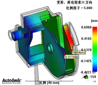
(A) Total deformation

(B) Deformation caused by uneven shrinkage
Figure 4 Deformation analysis results of the original plan plastic parts assembly direction
Plastic parts are converted into .stl format by UG and imported into MOLDFLOW. Two-layer surface model is used for mesh division. Finite element model is constructed with a unit side length of 1.0mm. According to actual production requirements, set up runners, gates and cooling water channels, grid division and attribute settings. Finite element model and its parameters are shown in Figure 3. Molding material is POM, brand: DupontDelrin311DPNC010. Molding process parameters are set as: mold temperature 90℃, melt temperature 215℃, push-out temperature 137℃, speed/pressure (V/P) control is converted to 99%, holding pressure is 80% of maximum injection pressure. Filling, cooling, holding pressure, warpage analysis, analysis results are shown in Figure 4.
02 Warpage analysis and optimization plan
It can be seen from Fig. 4 that plastic parts have severe inward shrinkage deformation on both sides, and inward shrinkage is about 0.822mm. In actual production, plastic parts shrink inward by 0.9mm, which cannot meet assembly requirements. According to experience, factors affecting warpage of plastic parts mainly include: plastic part structure, wall thickness, gate location, cooling. Printer drive connector has an open structure, plastic parts have low strength and are prone to shrink inward, which affects assembly of plastic parts. There are two common methods to improve such deformation: ① After plastic parts are formed, make orthopedic jigs to fix important size parts, and then take out to measure and use. This method needs to add a post-production process after molding, molding cycle is extended, and cost is high; ②Reverse direction modeling structure design is performed on warped part of plastic part, that is, pre-deformation treatment is performed. If amount of pre-deformation is not accurate, it is difficult to modify mold later (such as replacement of mold inserts or large-area repair welding of mold parts), which shorten service life of mold and increase production costs. Since gears need to be installed inside plastic parts, main assembly direction is X direction, and uneven shrinkage in X direction is main factor that causes warpage deformation. It adopts method of adding reinforcement ribs on both sides of plastic part opening, uses shrinkage properties(When plastic part cools, it shrinks towards thick material area) of POM material to balance shrinkage and deformation of plastic parts inward., balancing shrinkage deformation of plastic parts inward. Following uses MOLDFLOW software to analyze and verify effect of plastic parts improvement program.
03 Plastic parts optimization analysis and results comparison

Figure 5 Printer driver connection optimization scheme

(A) Total deformation

(B) Deformation caused by uneven shrinkage
Figure 6 Deformation analysis results of assembly direction of plastic parts after optimization
By adding 3.0mm*1.0mm reinforcing ribs on both sides of plastic part opening, as shown in Figure 5, optimized simulation results are shown in Figure 6, deformation on both sides of plastic part has been improved very well. Warpage deformation data before and after optimization are shown in Table 1.

(A) 3 Actual application effect

Figure 7 Comparison of plastic parts before and after optimization
According to MOLDFLOW analysis and optimization plan, improvement rate is >80%, according to optimization plan for mold design, processing and production trial production. After measurement, deformation of plastic parts is 0.13mm. Plastic parts before and after optimization are shown in Figure 7. From Figure 7, it can be seen that deformation defects of plastic parts shrinking inward after optimization have been greatly improved to meet requirements of assembly and use.
Recommended
Related
- Motor Support Plate Die-Casting Process Design and Optimization07-29
- A Comprehensive Guide to Hot Runner Thermostats in Injection Molds: How Experts Choose, Use, and Rep07-29
- Hydraulic Cylinder Core Pulling Design Considerations07-28
- Interpreting Four Key Parameters of Injection Molding and Their Impact on Product Quality07-28
- Taking silicone oil fan clutch housing as an example, let's discuss analytical logic of leakage07-27