
Give you a 4-cavity double-head plastic gear injection mold solution
Time:2020-06-22 10:08:25 / Popularity: / Source:
There are two identical gears on both sides of double-headed plastic gear, and gear meshing accuracy is required to be high. On parting of plastic parts, movable mold and fixed mold have tooth-shaped inserts with same shape. In order to ensure stability of molding and demolding of plastic parts, it is necessary to arrange a reasonable runner and introduce a sequential parting mechanism.
1 Plastic part process analysis
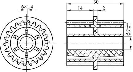
Figure 1 Double-end plastic gear
Double-headed plastic gear shown in Figure 1 needs to be produced in large quantities. Material is PPS. Gear parameters on both sides are same: module is 1mm, number of teeth is 22, and height is 15mm. Gears on both sides are connected by a reinforcing rib with a thickness of 2mm. Central hole is 7mm. Six stiffeners with a thickness of 1.4mm are evenly distributed on both sides. Gear meshing accuracy requirement is JGMA5. To ensure gear meshing accuracy, central hole ϕ7mm must be strictly controlled within accuracy of 0 ~ + 0.03 mm, gear needs to ensure roundness and coaxiality. In order to ensure that plastic parts of each cavity in mold meet specifications, each cavity must ensure same amount of feed during injection and holding process. Key to mold design is layout of gating system and demoulding of plastic parts.
2 Mold design
01 Cavity layout and gating system design
According to structural characteristics of plastic parts, in order to reduce production costs, 4-cavity layout is used. In order to make molten plastic flow uniformly after entering cavity, gate is selected at the position of rib on the top surface of plastic parts. In order to ensure roundness of outer peripheral gear of plastic parts and reduce welding marks as much as possible, three gates are arranged, diameter of each gate is ϕ1.0mm. Parting surface and gate position are shown in Figure 2.

Figure 2 Parting surface and gate location

Figure 3 runner design
Design of runner is shown in Figure 3. Purpose is to minimize heat difference between inside and outside of melt at turning position of runner, so that melt can maintain same flow velocity as far as possible in each of runners. Ultimately, make sure that each gate is balanced and that each cavity is fed same amount.
02 Mold structure design

Figure 4 Mold structure
1. Movable seat plate 2. Pad block 3. Core fixing plate 4. Movable model core 5. Movable template 6. Movable template 7. Fixed distance tie rod 8. Fixed template 9. Runner plate 10. Splitter tie rod 11. Fixed mold seat plate 12. Locating ring 13. Splitter rod spacer 14. Splitter insert 15. Fixed model core 16. Moving model core 17. Locking block 18. Moving model core block 19. Push rod fixing plate 20 .Push plate 21.Push plate pull rod 22.Guide sleeve 23.Pull rod wear sleeve 24.Push block 25.Limit screw 26.Guide sleeve 27.Guide sleeve 28.Guide column 29.Guide sleeve 30.Guide column 31.Guide Sleeve 32. limit screw 33. tie rod connection 34. cylindrical pin 35. push rod 36. spring 37. reset rod 38. gate sleeve 39. parting surface positioner 40. stroke fixed chain 41. push plate guide 42 Guide bush 43. Support post 44. Limit screw 45. Spring 46. Fixed mold toothed insert 47. Moving mold toothed insert
Mold structure is shown in Figure 4. Parting surface is selected on top surface of reinforcing rib in the middle of plastic parts, ribs are arranged on the side of movable mold. Because shapes of moving and fixed mold sides of plastic parts are almost same, resistance on moving and fixed mold sides is almost equal when plastic parts are demolded. In order to ensure meshing accuracy of peripheral gears, mold parts are not allowed to have a demolding slope. In this case, it is difficult to ensure that plastic part is stably wrapped on movable mold side during demolding process even if a large inclination is set at remaining part on fixed mold side of plastic parts. In order to solve this problem, a spring and a stop screw are provided at the bottom of toothed insert on fixed mold side, so that fixed toothed insert and fixed mold core have relative movement, toothed insert has a movement stroke of 2mm, which reduces demolding resistance on fixed mold side of plastic parts. At this time, core release angle of part other than fixed mold gear can be set to 1 °. In order to increase wrapping force on movable mold side of plastic parts, ensure dimensional accuracy of middle hole of plastic parts and gear meshing accuracy, mold release slope on movable mold side is set to 0. Although this can ensure that plastic part stays on movable mold side when parting surface is separated, resistance of plastic part when it is pushed out on movable mold side will be very large, so that gear meshing accuracy is affected by ejection depression of plastic parts, or push rod is broken because it cannot be pushed out during pushing process. To solve this problem, movable mold plate is divided into two pieces, toothed insert is installed on movable mold plate 6, core of middle hole of molded plastic part is installed on movable mold plate 5. After parting surface is opened and before plastic part is pushed out, movable mold plate 6 is separated from movable mold plate 5 so that central hole of plastic part is demoulded before other parts, thereby reducing resistance when plastic part is pushed out. Between movable mold plate 6 and movable mold plate 5, a rigid locking block 18 needs to be installed to ensure that movable mold plate 6 and movable mold plate 5 remain closed before parting surface is opened.
03 Mold working process
When mold is opened, movable mold is separated from fixed mold, fixed mold tooth insert is pushed out under force of spring, so that gears of fixed mold are released. At this time, movable mold plate 6 and movable mold plate 5 are kept tightly closed under action of locking mechanism. Mold continues to open. After stroke of fixed distance rod ends, movable mold plate 6 ends operation, and movable mold plate 5 continues to open until limit screw stroke ends. At this time, moving mold core on moving mold plate 5 will be separated from plastic part, and plastic part remains wrapped on moving mold core. Pusher pushes out plastic parts with less resistance to demolding. When mold is closed, push plate is reset, moving and fixed molds are closed, and next working cycle is performed.
Last article:Defect analysis and technological measures of die casting box
Next article:16 complete list of deburring process
Recommended
Related
- Motor Support Plate Die-Casting Process Design and Optimization07-29
- A Comprehensive Guide to Hot Runner Thermostats in Injection Molds: How Experts Choose, Use, and Rep07-29
- Hydraulic Cylinder Core Pulling Design Considerations07-28
- Interpreting Four Key Parameters of Injection Molding and Their Impact on Product Quality07-28
- Taking silicone oil fan clutch housing as an example, let's discuss analytical logic of leakage07-27