
Demoulding slope is not good, demould cannot be finished even if it is good!
Time:2020-05-04 08:51:56 / Popularity: / Source:
Draft angle is slope designed on both sides of cavity for convenience of ejection. Orientation of demould slope depends on internal and external dimensions of plastic parts.
Magnitude of demolding slope of plastic parts is related to nature, shrinkage rate, friction factor, wall thickness and geometric shape of plastic part. Hard plastics have a larger demolding angle than soft plastics; plastic parts with more complex shapes or more forming holes have a larger demolding angle; larger plastic parts with deeper holes have a smaller demolding slope; wall thickness increases, force of inner core to enclose core is large, and draft angle should be larger. Sometimes, in order to keep plastic parts in die or core when mold is opened, slope of side is intentionally reduced or hypotenuse is enlarged.
There is no certain rule for size of demolding angle. Most of them are determined by experience and according to depth of product.
In addition, molding method, wall thickness and choice of plastic are also considered. Generally speaking, for any side wall of a molded product, a certain amount of demolding slope is required in order to remove product from mold. Magnitude of demolding slope can vary from 0.2 ° to several degrees, depending on surrounding conditions, and generally between 0.5 ° and 1 ° is ideal.
Following points should be paid attention to when selecting draft angle:
a. Take direction of slope. Generally, inner hole is based on small end and conforms to drawing. Slope is obtained from enlarged direction. Shape is determined from big end and conforms to pattern. Slope is obtained from reduction direction. As shown below.
b. Where precision requirements of plastic parts are high, a smaller demoulding slope should be selected.
c. For higher and larger sizes, a smaller draft angle should be used.
d. If shrinkage of plastic parts is large, a larger slope value should be used.
e. When wall thickness of plastic part is thick, mold shrinkage will increase, and draft angle should adopt a larger value.
f. In general, draft angle is not included in tolerance of plastic parts.
g. Draft angle of transparent parts should be increased to avoid scratching. In general, draft angle of PS material should be greater than 3 °, ABS and PC material should be greater than 2 °.
h. Side wall of plastic parts with appearance treatment such as leather texture and sandblasting should be added with a draft angle of 3 ° ~ 5 °, depending on specific texture. General requirements for draft angle for reference purposes have been clearly exemplified on general sun print. The deeper texture depth, the larger stripping slope. Recommended value is 1 ° + H / 0.0254 ° (H is texture depth). For example, texture draft angle of 121 is generally 3 °, and texture draft angle of 122 is generally 5 °.
i. Slope of insertion surface is generally 1 ° ~ 3 °.
j. Draft angle of shell surface is greater than or equal to 3 °.
k. Except for shell surface, draft angle of other features of shell is 1 °. In particular, it can also be taken according to following principles: draft angle of ribs below 3mm height is 0.5 °, 3 to 5mm is 1 °, the rest is 1.5 °. Demolding slope of cavity below 3mm is 0.5 °, 3 ~ 5mm is 1 °, the rest is 1.5 °
Plastic part must have a sufficient demolding slope to avoid appearance of whitening, trauma and dragging. Demolding slope is related to properties of material, shape of parts, and surface requirements.
For parts in 3D file of parts that do not require draft angle, refer to general draft angle requirements in technical description. Appearance surface of part requires a smooth surface or a textured surface, demolding slope is also different. Slope value is as follows:
(1) Draft angle of small plastic parts with smooth surface on outer surface is 1˚, and draft angle of large plastic parts is 3˚;
(2) Outer surface etched surface Ra <6.3 and demolding slope is 3˚, Ra > 6.3 and demolding slope is 4˚;
(3) Outer surface texture surface Ra <3.2 and demolding slope / 3˚, Ra > 3.2 and demolding slope is 4˚.
For plastic parts of 3D model that has been built, Pro / E is used to check demolding slope. Steps are as follows:
Analysis ® Surface Analysis ®
Draft Check® [Give maximum slope value, select analysis
Part or Surface, determine directional surface corresponding to analysis] ® Compute.
Mold Design Guide-Plastic Structure
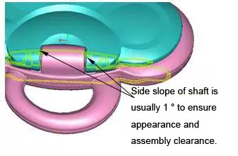
It should be noted that when modifying demolding angle of plastic parts, it is also necessary to ensure assembly relationship and appearance requirements of plastic parts, as shown in Figure.
1. Draft angle of plastic parts:
| Reference picture | Material name | Cavity (a1) | Core (a2) |
| Polyamide (common) | 20 ~ 40 ′ | 25 ~ 40 ′ | |
| Polyamide(reinforced) | 20 ~ 50 ′ | 20 ~ 40 ′ | |
| Polyethylene | 25 ~ 45 ′ | 20 ~ 45 ′ | |
| Polyoxymethylene | 35 ~ 1 ° 30 ′ | 30 ~ 1 ° | |
| Polychloroether | 25 ~ 45 ′ | 20 ~ 45 ′ | |
| Polycarbonate | 35 ~ 1 ° | 30 ~ 50 ′ | |
| Polystyrene | 35 ~ 1 ° 30 ′ | 30 ~ 1 ° | |
| Plexiglass | 35 ~ 1 ° 30 ′ | 30 ~ 1 ° | |
| ABS plastic | 40 ~ 1 ° 20 ′ | 30 ~ 1 ° |
There is no certain rule for size of demolding angle. Most of them are determined by experience and according to depth of product. In addition, molding method, wall thickness and choice of plastic are also considered.
In general, a certain amount of demolding slope is required for any side of a molded product in order to allow product to be smoothly ejected from mold. Magnitude of demolding slope is generally 0.5 ° ~ 1 °.
Following points should be noted when selecting demolding slope:
Surface of plastic part is smooth, requires high dimensional accuracy, and has a small shrinkage rate. A smaller demoulding slope, such as 0.5 °, should be used.
For higher and larger sizes, take smaller demolding slope according to actual calculation.
If shrinkage of plastic parts is large, a larger slope value should be selected.
When wall thickness of plastic part is thicker, mold shrinkage will increase, and demolding gradient should adopt a larger value.
Draft angle of transparent parts should be increased to avoid scratching. In general, draft angle of PS material should be greater than 2.5 °~3 °, ABS and PC material should be greater than 1.5 °~2 °.
Side walls of plastic parts with appearance treatment such as skin texture and sand blasting should be taken from 2 ° to 5 ° according to specific situation, depending on specific skin texture depth. The deeper skin texture, the greater draft.
When structure is designed to inserted in pairs, slope of insertion surface is generally 1 ° to 3 °.
Take direction of slope. Generally, inner hole is based on small end and conforms to drawing. Slope is obtained from enlarged direction. Shape is determined from big end and conforms to texture. Slope is obtained from reduced direction.
In general, draft angle is not included in tolerance of plastic parts.
Shell surface demolding slope is 3 ° or more. Except for shell surface, demolding slope of other features of shell is 1 ° as standard demolding slope. In particular, it can also be taken in accordance with following principles: demolding slope of ribs below 3mm height is 0.5 °, 3 to 5mm is 1 °, the rest is 1.5 °. Demolding slope of cavity below 3mm is 0.5 °, 3 ~ 5mm is 1 °, the rest is 1.5 °.
2. Determining wall thickness of plastic parts and processing wall thickness
It is important to properly determine wall thickness of plastic part. Wall thickness of plastic parts first depends on use requirements of plastic parts, including strength, quality cost, electrical performance, dimensional stability, and assembly requirements of parts. Generally, wall thickness has empirical values, which can be determined by referring to similarities.
Points to note are as follows:
Wall thickness of plastic part should be as uniform as possible to avoid too thin, too thick and abrupt wall thickness. If plastic part requires wall thickness change, it should use gradual change or circular arc transition, otherwise plastic parts will be deformed due to uneven shrinkage, affecting strength of plastic parts, affecting fluidity during injection molding. Thickness difference should be controlled within 25% of basic wall thickness as much as possible. Minimum wall thickness of entire component must not be less than 0.4mm, back surface is not a Class A surface, and area must not be greater than 100mm².
Wall thickness of plastic parts is generally in the range of 1 ~ 5mm. The most commonly used value is 2 to 3 mm.
Try not to design ribs and screw columns too thick. Generally, it is recommended to take half of body wall thickness, otherwise it is easy to cause appearance problems such as microcosms.
Try not to design part as a separate flat plate, size is very small, otherwise deformation will cause part to be uneven.
Minimum wall thickness of plastic products and recommended values of common wall thickness are shown in the table below:
| Recommended minimum and common wall thickness of plastic products (unit: mm) | ||||
| Engineering Plastics | Minimum wall thickness | Small product wall thickness | Medium product wall thickness | Large product wall thickness |
| Nylon (PA) | 0.45 | 0.76 | 1.50 | 2.40 ~ 3.20 |
| Polyethylene (PE) | 0.60 | 1.25 | 1.60 | 2.40 ~ 3.20 |
| Polystyrene (PS) | 0.75 | 1.25 | 1.60 | 3.20 ~ 5.40 |
| Modified polystyrene | 0.75 | 1.25 | 1.60 | 3.2 ~ 5.4 |
| Plexiglass (PMMA) (372) | 0.80 | 1.50 | 2.20 | 4.00 ~ 6.50 |
| Polypropylene (PP) | 0.85 | 1.45 | 1.75 | 2.40 ~ 3.20 |
| Polycarbonate (PC) | 0.95 | 1.80 |
2.30 |
3.00 ~ 4.50 |
| Polyoxymethylene (POM) | 0.8 |
1.40 |
1.60 |
2.40 ~ 3.20 |
| Polysulfone (PSU) | 0.95 | 1.80 | 2.30 | 3.00 ~ 4.50 |
| ABS | 0.80 | 1.50 | 2.20 | 2.40 ~ 3.20 |
| PC + ABS | 0.75 | 1.50 | 2.20 | 2.40 ~ 3.20 |
| Polyvinyl chloride (hard) | 1.15 |
1.60 |
1.80 |
3.2 ~ 5.8 |
| Polyvinyl chloride (soft) | 0.85 |
1.25 |
1.50 |
2.4 ~ 3.2 |
| Polyamide | 0.45 | 0.75 | 1.50 | 2.4 ~ 3.2 |
| Polyphenylene ether | 1.20 |
1.75 |
2.50 |
3.5 ~ 6.4 |
| Polysulfone | 0.95 | 1.80 | 2.30 | 3.0 ~ 4.5 |
| Chlorinated polyether | 0.90 |
1.35 |
1.80 |
2.5 ~ 3.4 |
| Cellulose acetate | 0.70 | 1.25 | 1.90 | 3.2 ~ 4.8 |
| Ethyl cellulose | 0.90 | 1.25 | 1.60 | 2.4 ~ 3.2 |
| Acrylic | 0.70 | 0.90 | 2.40 | 3.0 ~ 6.0 |
Recommended
Related
- Motor Support Plate Die-Casting Process Design and Optimization07-29
- A Comprehensive Guide to Hot Runner Thermostats in Injection Molds: How Experts Choose, Use, and Rep07-29
- Hydraulic Cylinder Core Pulling Design Considerations07-28
- Interpreting Four Key Parameters of Injection Molding and Their Impact on Product Quality07-28
- Taking silicone oil fan clutch housing as an example, let's discuss analytical logic of leakage07-27