
Paper conditioner injection moulding mould design points, can be used for similar product injection
Time:2020-04-30 08:32:29 / Popularity: / Source:
1. Introduction
Paper conditioner is a typical part of a desktop office printer. Each printer has a left and right paper adjuster, which has two main functions. The first is to adjust width of paper with a horizontal rack, and the second is to provide guidance for movement of paper.
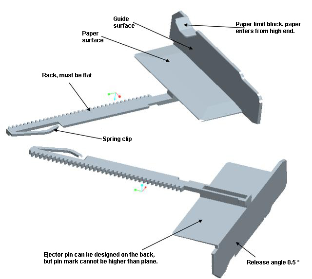
Paper-passing surface is also called paper surface. It refers to plastic parts that guide paper to travel during printing process, such as printers, fax machines, and copiers. Relevant surface of a plastic part that is in contact with paper, has supports and guides function, commonly referred to as a paper-passing surface. Paper plane is usually a flat surface, or it may be composed of some circular bones on plane. Customers generally have special requirements for products, such as not being able to set gates, thimbles on the paper. Do not have burrs, peaks so as not to affect passage of paper in the machine, contact surface should be as small as possible. Therefore, in injection moulding mould design, inserts are generally not designed on paper surface, and surface should be flat and highly polished to reduce resistance of paper passage.
Starting from function of paper regulator, plastic mold parts must not have burr, deformation and various appearance defects. Teeth of rack should be uniform in size. Entire rack should have good straightness, no internal stress, and recycled material should not exceed 5% when plastic mold parts are produced.
Starting from function of paper regulator, plastic mold parts must not have burr, deformation and various appearance defects. Teeth of rack should be uniform in size. Entire rack should have good straightness, no internal stress, and recycled material should not exceed 5% when plastic mold parts are produced.

2. Plastic analysis
Paper regulator product is shown in Figure 1. Maximum dimensions are 132mm X 95mm X 28.20mm, material is ABS, shrinkage is 1.005, and weight is 9.70g. Slider needs to be designed in two parts. Lower part of paper limiter needs to be designed with a slider. Since guide surface cannot have inlay mark, slider must be a large slider containing entire guide surface. These two bottoms of large end of plastic mold parts need to be designed to release mold.
3. Injection moulding mould design points
(1) Mold layout:
Plastic structure is unique. Two parts need to design slider. Mold structure is complex. For this purpose, mold structure of 1 out 1 is designed. See Fig. 2. Mold base is standard small water nozzle mold LKM DCI2530. In order to facilitate wire cutting process, rack part is designed as a mushroom type insert, as shown in Figure 3.
(2) Injection method:
Gate surface of plastic mold parts, top surface and side surface of guide surface cannot be designed with a gate. Rack is difficult to design gate near paper-passing surface due to presence of front-mode oblique slide slider. Pin-point gate mold is designed to feed glue on the head of plastic rack through water nozzle. Gate is manually trimmed after molding, where glue does not affect function of rack. Dimensions of runners and gates are shown in Figure 2.
(3) Plastic parts ejection:
Parting surface of plastic mold parts is stepped, rack is in rear mold, glue surface of paper is all in front mold, parting surface is shown in Fig. 3. Demoulding of plastic part is ejected through ejector pin, and ejecting mechanism has a middle support in ejector plate. Thimble print must not exceed flat surface of plastic mold parts to avoid affecting assembly of plastic part.
(4) Design of cooling water transport:
Straight-type water transport is designed for front and rear mold cores, nozzle push plate. See Figure 2 for mold.
(5) Lateral core pulling mechanism design:
Large sliding block in the lower part of paper limiting block belongs to front mold sliding block. After analysis, it is designed as mold structure of front mold oblique projectile. When mold is opened, front mold oblique slide slider (key 13) gradually slides out of plastic mold parts under action of two ¢16*80 springs (piece 12). Hook acts as an auxiliary spring. Two small buckles on end face are designed as a rear mold slide, driven by a slanted guide post.
(6) About injection moulding mould design scheme:
Here front mold oblique slide slider can not be designed as rear mold large oblique top. Because after ejection of rear mold by large curved top of rear mold, plastic parts are difficult to take out and movement is out of control. Therefore, selection of mold opening direction is very critical.
(7) Steel selection:
Front and rear mold cores, large sliders are all selected from Japanese pre-hardened steel NAK80, moving parts are nitrided to improve life of mold.


4. Conclusion
Use of this mold over past few years shows that injection moulding mould design is reasonable, mold life is long, durable, and creates value for customer, which can be used as a reference for injection moulding mould design of similar products.
Recommended
Related
- Motor Support Plate Die-Casting Process Design and Optimization07-29
- A Comprehensive Guide to Hot Runner Thermostats in Injection Molds: How Experts Choose, Use, and Rep07-29
- Hydraulic Cylinder Core Pulling Design Considerations07-28
- Interpreting Four Key Parameters of Injection Molding and Their Impact on Product Quality07-28
- Taking silicone oil fan clutch housing as an example, let's discuss analytical logic of leakage07-27