
Application of Bernoulli effect in air ejection of thin-walled plastic parts
Time:2022-09-15 09:18:48 / Popularity: / Source:
【Abstract】Structural characteristics of transparent plastic cups for aviation are analyzed, mold structure, design characteristics, material selection and demoulding methods of thin-walled plastic parts are introduced, and application of Bernoulli effect in compressed air ejection of thin-walled parts is introduced. It has been verified by manufacturer that mold structure design is reasonable and fully meets structural and technological thin-walled cup, which can be used for reference by engineers and technicians engaged in design and manufacture of injection molds.
1 Introduction
Thin-walled plastic parts have advantages of material saving and low cost, are more and more widely used in disposable tableware and other fields. Aviation cutlery thin-walled cups are disposable products, using PP material, with a wall thickness of 0.5mm. Outer surface of thin-walled cup is required to be smooth, with clear lines, no scratches, weld marks, deformation, and no thimble marks on inner surface. Due to thin wall of thin-walled cup, in order to reduce cost and shorten injection cycle, mold injection cycle is required to be controlled within 6s, which poses a great challenge to injection molding technology. Therefore, injection molding of thin-walled cups not only places high requirements on injection molding machine, but also puts forward higher requirements on injection mold. This paper introduces application of Bernoulli effect in compressed air ejection through thin-walled cup injection mold.
2 Mold technical requirements
Production volume of thin-walled cups is huge, and plastic parts are required to have low cost. In order to shorten part molding cycle, injection mold needs to use a hot runner system. Because there is no cooling time limit of runner system, plastic parts can be ejected in time after being formed and solidified. At the same time, there is no runner condensate in hot runner mold, so there is no waste of raw materials. Plastic part is finished after being formed by hot runner mold. There is no need to trim gate, recycle and process runner condensate, which is conducive to production automation.
In order to adapt to production batch of thin-walled cups, cavity ranking of plastic parts is a multi-cavity mold, and this auxiliary mold adopts a cavity ranking of 16 cavities. During molding process of thin-walled cup plastic mold, temperature of plastic melt is accurately controlled in runner system. Plastic flows into each cavity in a more uniform state, resulting in consistent quality plastic parts. In addition, gate quality of plastic parts formed by hot runner is good, residual stress after demolding is low, and deformation of plastic parts is small. Therefore, use of hot runner injection can reduce waste and improve quality of plastic parts.
Due to high smoothness of mold surface, it is necessary to use Swedish ASSAB mold steel S136, heat treatment 48~52HRC, so that mold has characteristics of precision, high efficiency and long life, is suitable for high-speed and high-pressure injection production.
Thin-walled cup mold is a multi-cavity mold, which needs to withstand high speed and high pressure during injection molding. In order to effectively prevent eccentric dislocation of mold, each cavity needs to design an independent movable and fixed mold self-locking structure. For multi-cavity precision molds for round plastic parts, parts of each cavity are required to be interchangeable.
Thin-walled cup mold requires injection cycle to be controlled within 6s, which puts forward high requirements for cooling system of movable and fixed molds. It is required that cooling water circuit is designed evenly, air circuit and water circuit are staggered, compressed air also has a cooling effect while being ejected.
Thin-walled cup molds require compressed air to be ejected, and to make full use of air path design, influence of Bernoulli effect on falling of thin-walled plastic parts must be considered.
3 Mold structure design
Figure 1 shows disposable aviation cup mold. Mold is a multi-cavity mold with 16 cavities. Injection molding cycle is 6s, and hot runner is used for molding. Fixed mold insert 3 is designed at the bottom of cavity 13, which is convenient for exhaust and processing. Cooling water and air passages are designed between hot nozzle bushing and fixed die insert 3. Sealing ring 9 and sealing ring 11 seal cooling water circuit to prevent leakage from air circuit. Air on fixed mold side enters from air path between fixed mold insert 3 and hot runner plate 4, then divides into two paths in fixed mold insert 3, enters cavity along gap between hot nozzle bushing and stationary mold insert 3, sealing ring 25, sealing ring 26 and sealing ring 27 seal stationary mold insert 3 and cavity 13; The other way is to enter cavity along gap between fixed mold insert 3 and cavity 13, sealing ring 28 seals space between fixed mold insert 3 and hot runner plate 4 to prevent compressed air from leaking out of mold and ensure air pressure in cavity.
Core part is divided into two parts, beryllium copper insert 12 is located at the top of core 15, which is the most typical design. After cooling water circuit enters from center of core, 8 water-carrying circuits in shape of spokes along circumference cool core. Sealing ring 21, sealing ring 22 and sealing ring 23 seal cooling circuit. Gap between beryllium copper insert 12 and core 15 is also designed with an inner circuit of compressed air. Air circuit is also designed with 8 spokes along circumferential direction, angle is staggered from cooling water circuit to avoid cooling water.
Blowing of parting surface is undertaken by ventilation rod 31 . After parting surface is opened, compressed air enters through ventilation hole 29, high-pressure gas blows ventilation rod 31, air is ejected from top blowing port, plastic parts are lifted by 8 air flows in the shape of a spoke in circumferential direction. Air flow of fixed mold is blown out from bottom of air cup and side near bottom, air flow in cup and external air flow form a combined force to demould plastic part.
Intake seat 37 and intake seat 41 are fixed to fixed mold, and valve stem 38 is fixed to movable mold. Compressed air enters mold through connecting hoses of air inlet seat 37 and air inlet seat 41 . Valve stem 38 moves along mold opening direction to control opening and closing of air inlet 40.
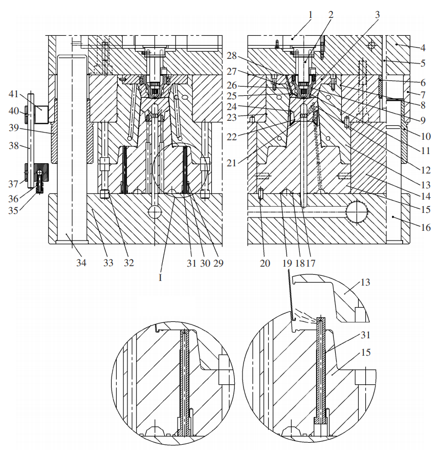
Figure 1 Pneumatic ejection die for aviation cup
1. Diverter plate 2. Hot nozzle 3. Fixed mold insert 4. Hot runner plate 5. Positioning pin 6. Bushing 7. Fixed template 8. Sealing ring A 9. Sealing ring B 10. Guide sleeve 11. Sealing ring C 12. Beryllium copper insert 13. Cavity 14. Moving template 15. Core 16. Guide post 17. Sealing ring D 18. Sealing ring E 19. Sealing ring F 20. Positioning pin 21. Sealing ring G 22. Sealing ring H 23. Sealing ring I 24. Sealing ring J 25. Sealing ring K 26. Sealing ring L 27. Sealing ring M 28. Sealing ring N 29. Ventilation hole 30. Sealing ring O 31. Ventilation rod 32. Bolt 33. Moving Die seat plate 34. Guide post 35. Ventilation bolt 36. Adjusting nut 37. Inlet seat 38. Valve stem 39. Guide sleeve 40. Inlet hole 41. Inlet seat
1. Diverter plate 2. Hot nozzle 3. Fixed mold insert 4. Hot runner plate 5. Positioning pin 6. Bushing 7. Fixed template 8. Sealing ring A 9. Sealing ring B 10. Guide sleeve 11. Sealing ring C 12. Beryllium copper insert 13. Cavity 14. Moving template 15. Core 16. Guide post 17. Sealing ring D 18. Sealing ring E 19. Sealing ring F 20. Positioning pin 21. Sealing ring G 22. Sealing ring H 23. Sealing ring I 24. Sealing ring J 25. Sealing ring K 26. Sealing ring L 27. Sealing ring M 28. Sealing ring N 29. Ventilation hole 30. Sealing ring O 31. Ventilation rod 32. Bolt 33. Moving Die seat plate 34. Guide post 35. Ventilation bolt 36. Adjusting nut 37. Inlet seat 38. Valve stem 39. Guide sleeve 40. Inlet hole 41. Inlet seat
4 Bernoulli effect
Any cavity and core that have a vacuum phenomenon when mold is opened should be designed with an air bleed device. During pneumatic ejection, compressed air is used to set air passages and small ejection air holes on mold to directly blow plastic parts out of product without leaving ejection marks. It is suitable for thin or long cylindrical plastic parts.
Compressed air ejection is suitable for any cup-shaped plastic part. When compressed air enters between core and plastic part, there is enough pressure to push plastic part out of core. For thin-walled cup parts, plastic parts may fly out of core and fly into cavity due to force, affecting injection molding cycle. When using air ejection, Bernoulli effect must be considered. Side walls are within a certain range of angles, and this effect will occur if location of air entering core is not properly designed. Air flows out between core and plastic part, at the open end of plastic part, a low pressure state will be formed inside plastic part, which will counteract force exerted by compressed air on plastic part.
Consequence of this effect is that plastic part stops after being ejected for a certain distance, then floats in air and does not fall from mold core. Blowing port can prevent occurrence of Bernoulli effect, air flow caused by air pressure and airflow can effectively solve this problem, it is a common practice to blow air from cavity side and core side of fixed mold. Another method is to increase blowing at parting surface in addition to blowing on the side of fixed mold cavity and core, composite airflow can effectively blow plastic parts off mold.
5 Design points of compressed air ejector
Design points of compressed air ejection are as follows: ①Air pressure entering cavity and core can be adjusted, and size of vent hole can be adjusted; ②According to mold opening stroke, moving distance of valve stem is calculated, opening and closing of air inlet is automatically controlled; ③According to requirements of injection cycle, control ventilation time, generally less than 1s; ④Blowing sequence of cavity and core should be designed reasonably and can be adjusted at the same time;
In addition, mold cavity ejected by compressed air needs to improve machining accuracy to avoid plastic overflowing into gap between cavities. Compressed air must be purified so that no moisture, oil and impurities enter air channel. In production of high-grade food packaging materials and containers for medical supplies, when compressed air directly contacts surface of plastic parts, air should be sterilized before connecting.
Pneumatic demolding is often used for launch of large, deep cavity, thin-walled or soft plastic parts. This kind of mold must be equipped with structures such as air passages and air valves in mold. After mold is opened, compressed air (usually 0.5~0.6MPa) enters cavity through air path and air valve, plastic part is released from mold.
Adhesion force of thin-walled plastic parts to fixed mold inserts and wrapping force to movable mold are very large. Due to vacuum adsorption, this plastic part is easy to stay on the side of fixed mold when mold is opened, or it is uncertain which side to stay on. In order to ensure that plastic parts remain in movable mold when mold is opened, an intake valve structure must be set on fixed mold side. When mold is opened, fixed mold intake valve is opened to push plastic parts out of fixed mold. For deep cavity plastic parts that cannot be pushed out by a push rod, an air bleed device is designed to overcome vacuum, method of pushing out by air pressure is effective.
Thin-walled plastic parts have very high requirements on injection process, requiring high speed and high pressure, and must be injected with a high-speed injection molding machine.
6 Conclusion
Thin shell molding usually uses a high-performance special mold, which must be able to withstand high pressure, high-speed injection, high rigidity, high strength, and excellent venting, cooling and good ejection performance. According to structural characteristics of thin-walled and deep-cavity plastic parts, adverse effects of Bernoulli effect can be effectively overcome by designing a reasonable cooling circuit and compressed air path, positive factors of Bernoulli effect can be used to make extrusion process of plastic parts stable and mold to run at high speed and high efficiency. Judging from use of mold since it was put into production, all indicators fully meet requirements of mold style book.
Recommended
Related
- Motor Support Plate Die-Casting Process Design and Optimization07-29
- A Comprehensive Guide to Hot Runner Thermostats in Injection Molds: How Experts Choose, Use, and Rep07-29
- Hydraulic Cylinder Core Pulling Design Considerations07-28
- Interpreting Four Key Parameters of Injection Molding and Their Impact on Product Quality07-28
- Taking silicone oil fan clutch housing as an example, let's discuss analytical logic of leakage07-27