
Medical device substrate injection mold design
Time:2022-09-09 08:31:36 / Popularity: / Source:
Medical device substrate is a substrate used for a medical device to be fixed on the wall. Plastic part is divided into two parts to form a group. Product is shown in Figure 1. Maximum dimension of large product is 356.90 mm * 226.80 mm * 45.50 mm, average thickness of plastic part is 2.50 mm, plastic part material is ABS, shrinkage rate is 1.005, and weight of large plastic part is 297.93 grams. Technical requirements for plastic parts are that there shall be no defects such as peaks, underfilling, flow lines, pores, warpage deformation, silver lines, cold materials, and spray lines.
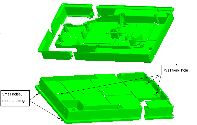
Figure 1 Product map of medical device substrates
It can be seen from Fig. 1 that plastic part is a flat rectangular shell, and two parts are closely attached together after being assembled to form a complete rectangle. On mold, two parts are jointly opened on a set of molds to form a family mold. There are two sinking features on the front of plastic part. Mold needs to consider dividing inserts to solve problem of sticking to front mold; on the surface, there are 3 long holes for wall installation. There are many screw posts and bone positions on the back of plastic part, design of insert and ejection of plastic part need to be carefully considered. There are two circular holes on the bottom surface of one end of plastic part, and a tunnel-type slider needs to be designed to solve core-pulling problem.
Mold design cavity ranking is 1 cavity, and mold base is CI 4560 A120 B110 C110. Panel and bottom plate of mold are enlarged in size to meet NB400-ton injection molding machine code mold. This British injection molding machine adds two U-shaped notches on the side of mold for safety of code mold, which is convenient for positioning of code mold. Positioning pins are designed between panel and A plate as well as between B plate, square iron and bottom plate to increase rigidity of mold. On parting surface of mold, a taper positioning block is designed on each side, which can resist lateral force in cavity during injection molding.
3D drawing of mold design is shown in Figure 2. When designing mold, place side with the most bone in movable mold and the other side in fixed mold. Gating system adopts direct gate of main channel, gate is directly on the surface of plastic part, and it is removed with electric shears after molding.

Figure 2 3d drawing of mold design

Figure 3 Slide block and its parting surface design

Figure 4 Structure of back mold tunnel slider
Design of slider and its parting surface is shown in Figure 3, and structure of rear mold tunnel slider is shown in Figure 4. Wear-resistant plate on inclined surface of slider is fixed on wedge, and wear-resistant plate is also designed on the bottom surface of slider. Slider is driven by an inclined guide column, and slider insert is clamped on slider seat with a T-slot. T-shaped slot of slider seat is processed into a through slot by wire cutting, which is very convenient.
Plastic parts need to be closely attached to wall, therefore, plastic parts must be flat to fit. Therefore, mold design must overcome internal stress of plastic parts and prevent plastic parts from deforming. Design of mold cooling system is shown in Figure 5. Fixed die is cooled by straight-through water, with the highest efficiency. Movable mold is cooled by a pond, which can be effectively cooled to all parts of core.
If cooling rate is balanced, shrinkage rate is also same, and deformation of plastic part is also small, so deformation of plastic part can be prevented. When plastic part is thick and cooling is not sufficient, surface will shrink and sag. Even if thickness of plastic part is appropriate, if cooling method is not good and cooling speed of each part of molded product is different, it will cause warping due to thermal shrinkage. Therefore, it is necessary to cool all parts of mold evenly.
If cooling system design of mold is unreasonable or mold temperature is not properly controlled, plastic part will be insufficiently cooled, which will cause plastic part to warp and deform. For control of mold temperature, temperature difference between fixed mold and movable mold, mold core and mold wall, mold wall and insert should be determined according to structural characteristics of product, so as to control cooling and shrinkage speed of each part of mold. After demolding, it tends to bend in direction of traction on the side with higher temperature to offset difference in orientation shrinkage and prevent plastic parts from warping and deforming according to orientation law. For plastic parts with completely symmetrical shape and structure, mold temperature should be kept consistent accordingly, so that cooling of each part of plastic part is uniform.
For water transport circuit designed by mold cooling system, a special nameplate should be made and customized on mold to facilitate injection molding worker to connect the water transport.

Figure 5 Cooling system design
Ejection of plastic parts is completed by thimble, cylinder and flat thimble. Mid-tower is designed on thimble plate, which provides guidance for thimble and flat thimble, prolongs service life. At the same time, a travel switch is designed on ejector plate to detect and determine return position of system.
Ejection of plastic parts is completed by thimble, cylinder and flat thimble. Mid-tower is designed on thimble plate, which provides guidance for thimble and flat thimble, prolongs service life. At the same time, a travel switch is designed on ejector plate to detect and determine return position of system.
Last article:Drying of raw materials before plastic injection molding
Next article:This will protect your injection molding machine!
Recommended
Related
- Motor Support Plate Die-Casting Process Design and Optimization07-29
- A Comprehensive Guide to Hot Runner Thermostats in Injection Molds: How Experts Choose, Use, and Rep07-29
- Hydraulic Cylinder Core Pulling Design Considerations07-28
- Interpreting Four Key Parameters of Injection Molding and Their Impact on Product Quality07-28
- Taking silicone oil fan clutch housing as an example, let's discuss analytical logic of leakage07-27