
Application of Moldflow Software in Plastic Injection Mould Design
Time:2019-04-15 10:58:39 / Popularity: / Source:
- Basic process of injection molding manufacturing process
- Application of Moldflow software
Under auxiliary analysis of Moldflow, optimal parameters of wall thickness of plastic parts in practical application can be obtained, thereby effectively improving structural stability of plastic products made by injection moulding, reducing production cycle and cost, ensuring that plastic products made by injection moulding achieves a complete filling effect.
2.2 Optimize mold structure
Through Moldflow analysis, optimal gate position and quantity can be obtained, cooling system and runner system can be calculated to optimize size of each system in tool processing, thereby reducing number of mold repairs.
2.3 Optimize production process parameters
Moldflow can also obtain optimum mold temperature, solution temperature, holding pressure, injection pressure, holding time, etc. in design and production of injection molding, which greatly improves quality of injection molding production.
- Example application analysis
3.1 Preparation before injection molding manufacturing process
Firstly, it is imported into Moldflow through 3D drawing STL. Since product is a mobile phone case, thickness is thin, and network model is used for division. Default variable length is used for division, mesh is strictly forbidden to overlap. Use auto-patching in processing tool to fix cross-overlap problem that may exist in search grid, adjust cell aspect ratio, and make intersecting unit zero. In general, the smaller average side length of mesh, the higher matching rate and accuracy.
After grid processing is completed, process conditions are set. Considering that plastic product is a mobile phone, in view of functional requirements and application requirements, amount of deformation in use is minimized, and material is selected to be ABS+PC synthetic material, and surface temperature of injection moulding die is set to 80℃. Solution temperature was 260℃, and other parameters adopt default values.
Number of gates and position analysis, using gate location and analysis functions in Moldflow for analysis, resulting in best settings. Number and location of gates are different. Path, distance and resistance of melted colloid flow are different. Production process, technology, appearance and molding problems of product are comprehensively considered and analyzed. Position and quantity of gate are determined according to analysis results. In combination with mobile phone mold making, gate is selected in one, two and four injection molding forms, and gate position is selected in the middle of plastic part.
3.2 Moldflow flow simulation results analysis
Injection patterns of three different gates were analyzed to study effects on filling, holding pressure and warpage, so as to obtain the best filling state.
3.2.1 Effect on fill time
Fill time can be analyzed by leading edge expansion of melt flow and better presented in the form of a cloud map. If spacing of cloud maps is very uniform, it also shows that melt is very stable in flow and filling of plastic parts is very balanced. Difference between shortest time and longest time used by plastic solution to reach end of cavity can also directly reflect degree of imbalance in cavity flow. Of course, the greater time difference, the more unbalanced. Therefore, try to choose a smaller time difference to keep balance of melt in flow. Moldflow is used to analyze filling time of three different ways, results show that melt fills end time with a single gate of 1.02 s, while double gate is 1.16 s, while four gates are 1.30 s.
3.2.2 Effect on pressure distribution
Moldflow was used to simulate pressure distribution. Results show that pressure distribution and die pressure distribution of product. When pressure is maintained, pressure of die has a great influence on volume shrinkage rate, so that pressure fluctuation in cavity is relatively small when pressure is maintained. Simulation results show that fluctuation space of die pressure in the case of single gate is (0~55.24) MPa, partial pressure drop in small area between upper end of plastic part and gate is obvious; Pressure fluctuation of double gate is (0~49.56) MPa, which becomes larger in upper end region of plastic part, but pressure at gate position is relatively stable and change is not large; Plastic pressure of four gates is (0~ 45.22) MPa, similar to double gate, but pressure in upper end region has a certain change, but variation is small. Comprehensive pressure distribution shows that four gate pressure changes are relatively small and die pressure is low, so volume shrinkage of product in this injection molding form is small, and quality of product is also more easily controlled.
3.2.3 Effect on cavitation distribution
When melt from different directions flows to same position, it may cause generation of air pockets. In plastic parts, appearance of air pockets and weld marks will seriously affect quality of workpiece. To this end, Moldflow was used to simulate cavitation distribution, and three injection conditions were analyzed. Results showed that positions of cavitation can be discharged in three cases without affecting appearance of products made by injection moulding. Other locations can also be removed by appropriately adjusting injection time, wall thickness of part, and so on.
3.2.4 Effect on weld mark
Simulation results of weld line show that single gates produce the most weld marks, and more parts are distributed as button areas. Treatment of such weld line can be realized by discharging air in the gap of template, although there is a large weld line, but it will not be trapped; Number of weld marks produced by injection molding method of four gates is significantly reduced, but length of weld marks is much higher than other methods, especially in the middle of part, this length is very long, its existence greatly affects structural strength of part; double gate has fewer weld lines, and most of it appears on inner wall of part, so it does not seriously affect appearance and structural quality of part.
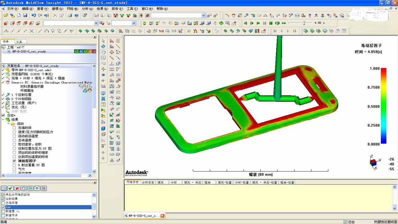
3.3 Analysis of results
Simulation analysis is given from filling time, cavitation distribution and pressure distribution, and following conclusions are drawn: single gate can not meet appearance requirements, and structural performance of four gates is not up to standard, so comprehensive analysis uses double gate injection molding to ensure a balanced appearance and structural quality.
- Conclusion
Recommended
Related
- Motor Support Plate Die-Casting Process Design and Optimization07-29
- A Comprehensive Guide to Hot Runner Thermostats in Injection Molds: How Experts Choose, Use, and Rep07-29
- Hydraulic Cylinder Core Pulling Design Considerations07-28
- Interpreting Four Key Parameters of Injection Molding and Their Impact on Product Quality07-28
- Taking silicone oil fan clutch housing as an example, let's discuss analytical logic of leakage07-27