
Main points of design of injection mold for automatic thread removal of air induction joint and face
Time:2020-09-08 10:23:47 / Popularity: / Source:
Main points of design of injection mold for automatic thread removal of air induction joint
Maximum external dimensions of air-entraining joint products are ø1.2893" * 1.3698", average plastic thickness of plastic parts is 0.1", material of plastic parts is ABS, and shrinkage is 1.006. Technical requirements of plastic parts are that there should be no peaks, injection dissatisfaction, flow lines, pores, warpage, silver lines, cold materials, spray lines, air bubbles and so on. No mold release agent should be used in the molding of plastic parts.
Plastic part is a circular rotating body plastic part, front mold has a ring of grooves, and inner wall of rear mold has inch internal threads 1/2-14. This thread does not lead to top of inner wall. Shape of plastic part is tapered and gradually transitions from large to small. After analysis, parting surface of plastic part is a simple plane. Thread and plastic part are on same side of parting surface. At this time, faced with choice of thread design in front mold off thread or back mold off thread, main basis of this choice is how to design will facilitate ejection of plastic parts. This thread must be fully automatic rotary thread removal, not strong. All mold design adopts British standard parts. Mold design style is style of North American mold. Mold design drawing is shown in Figure 1.
Plastic part is a circular rotating body plastic part, front mold has a ring of grooves, and inner wall of rear mold has inch internal threads 1/2-14. This thread does not lead to top of inner wall. Shape of plastic part is tapered and gradually transitions from large to small. After analysis, parting surface of plastic part is a simple plane. Thread and plastic part are on same side of parting surface. At this time, faced with choice of thread design in front mold off thread or back mold off thread, main basis of this choice is how to design will facilitate ejection of plastic parts. This thread must be fully automatic rotary thread removal, not strong. All mold design adopts British standard parts. Mold design style is style of North American mold. Mold design drawing is shown in Figure 1.


There are many ways to automatically dethread, common ones include hydraulic motor dethreading, cylinder gear rack dethreading, screw rod dethreading, bevel gear dethreading, and use of mold opening gear rack to dethread and so on. Considering that plastic parts can be ejected by cylinder, thread-removing mechanism is designed in rear mold. Plastic parts can only be ejected after thread is removed. Therefore, gear rack of oil cylinder is designed to be dethreaded. This kind of mechanism mainly uses hydraulic cylinder to drive rack, rack then drives gear to achieve work. Disadvantage of this kind of mechanism is that oil cylinder and rack will occupy a large space on mold, making overall shape of mold look a bit huge, which makes it difficult to lift and transport mold. But this structure has good stability and reliability, so it is widely used.


Mold is a mold in North America. Due to thread removal, mold base is a non-standard mold base. With reference to DME mold base structure, all standard parts are imperial. Layout of mold is 2 cavity, injection method is horn feeding, submerged front mold can be automatically cut off after mold is opened. Inserts of front and rear molds are all round, and water is transported around circumference of insert to achieve uniform cooling. In addition, outer diameters of front and rear mold inserts are designed to have two different sizes and diameters, are connected by a slope. Purpose of this design is to prevent rubber ring from being easily crushed during assembly.
Calculation of thread removal parameters is very critical. Please refer to mold design drawing 1. Note that gear parameters are all inch gears, that is, diameter control gears. For calculations, please refer to mechanical design manual. Calculated number of rotations is 6.24. For safety, it is calculated according to 6.3. Number of teeth of three transmission gears G1, G2, and G3 are 14, 36, and 18, respectively. Calculated rack travel is 11.54", and actual design is 11.75".
Calculation of thread removal parameters is very critical. Please refer to mold design drawing 1. Note that gear parameters are all inch gears, that is, diameter control gears. For calculations, please refer to mechanical design manual. Calculated number of rotations is 6.24. For safety, it is calculated according to 6.3. Number of teeth of three transmission gears G1, G2, and G3 are 14, 36, and 18, respectively. Calculated rack travel is 11.54", and actual design is 11.75".

Thread of plastic part does not lead to step. Therefore, a core must be designed inside thread core, which can be used to design cooling system. Threaded sleeve shown in section D-D has 15 holes on circumference, which is convenient for adjustment during assembly. There is a reasonable gap between threaded core, inner core and outer cylinder in diameter direction, so as not to burn to death when working. These key parts need to be processed with high-quality steel, heat-treated and have high processing accuracy. After unthreading is completed, top rod of injection molding machine pushes mold ejector rod to push ejector pin plate, and cylinder at the bottom of plastic part ejects plastic part.


Figure 1 Mould drawing of the air induction joint
Design of injection mold for face frame of butterfly bracket
Butterfly bracket is a bracket for a baby's pacifier and needs to be in close contact with baby's face. Product of butterfly bracket shell is shown in Figure 1. Maximum external dimensions of product are 58.40 mm * 40.05 mm *16.64 mm, average plastic thickness of plastic parts is 1.50 mm, plastic parts are made of food grade PP, shrinkage rate is 1.016, and weight of plastic parts is 3.84 grams. Technical requirements for plastic parts are that there must be no defects such as peaks, injection dissatisfaction, flow lines, pores, warpage, silver lines, cold materials, spray lines, etc.

It can be seen from Figure 1 that plastic part is shaped as a butterfly-shaped housing. There are blind grooves and through holes in the side walls of two half circles at the bottom, and slider core needs to be designed. Slider is a tunnel slider, and two sliders need to pass through rear die. Difficulty of mold design is that line of edge of plastic part cannot exceed 0.01, special attention needs to be paid in CNC machining and polishing process.
There is a high demand for matching of front and rear mold cores of mold. Parting surface of plastic part is an irregular curved surface, and material PP has excellent fluidity. Edges of plastic parts are all round and curved, which requires a smooth feel. Large round hole in the middle and six small round holes on both sides are rounded edges, which requires front and rear mold cores to be accurately clamped and maintain mold clamping accuracy. Four corners of front and rear mold cores are positioned at 5° tiger's mouth to ensure accurate mold clamping. Pay attention to angle when designing tiger's mouth, and use angle below 5° as much as possible. Mold steel is made of NAK80 steel imported from Japan, which is a pre-hardened steel with good processing performance and suitable for polishing. Front and rear mold core needs to achieve a mold with a line segment difference of less than 0.03, you need to pay attention to following points:
1) Mold base positioning and guidance: mold is well positioned at level 3. Use 0° positioning blocks whenever possible. Slope of tiger's mouth does not exceed 5°; insertion angle of positioning element is smaller than insertion angle of mold insert.
2) Mold steel: When purchasing, order precision gong abrasives as much as possible, and geometrical tolerance of verticality in each direction should not exceed 0.02; material hardness should be above HRC40. Use heat-treated steel as much as possible to increase hardness of parting surface to avoid collapse.

Figure 1 Product picture of butterfly bracket face shell
3) For some plastic parts with holes, disassembling inserts is beneficial to matching processing of front and rear molds to improve processing accuracy.
4) For curved parting surfaces, high-speed CNC must be used and processed with new cutters. When programming, you need to summarize software's toolpath performance characteristics and select a reasonable processing path to improve processing accuracy and save processing time. When flying molds, remember not to repair with files and whetstones.
5) When polishing, front and back molds can be combined together to polish mold, as far as possible. It needs to be processed by experienced polishers to avoid mistakes.
6) When injection molding, you need to pay attention to mold clamping accuracy of injection molding machine. You cannot use an injection molding machine with poor mold clamping accuracy to avoid damage to mold. In addition, it should be noted that injection molding machine must have sufficient clamping force.
Mold design cavity layout is 4 cavity. Since plastic parts need to be designed with sliders on both sides, mold design layout is a linear type. Mold base is a simplified thin nozzle FCI-2030-A60-B90-C70, design of casting system is that fine nozzle turns into a latent gate, and it is submerged in the center of plastic part to rear mold. Shape of runner is S-shaped, and cross-section is trapezoidal.
Both front and rear molds are designed with a cooling circuit, which uses straight-through water transport to form an independent cycle to cool mold core.
Sliders on both sides are longer and are driven by two diagonal guide columns respectively. After mold sample was confirmed, slider was DLC coated to increase wear resistance.

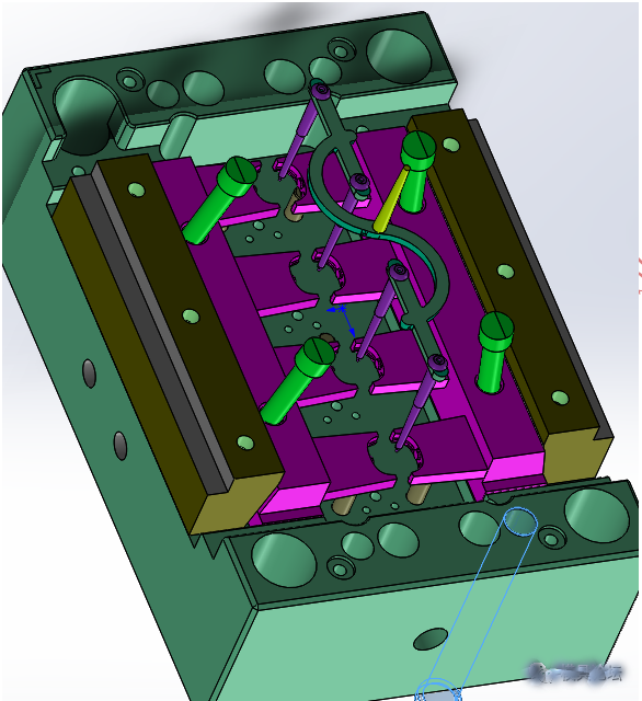
Figure 2 Die bracket mould drawing

Figure 3 Sample photos
Recommended
Related
- Motor Support Plate Die-Casting Process Design and Optimization07-29
- A Comprehensive Guide to Hot Runner Thermostats in Injection Molds: How Experts Choose, Use, and Rep07-29
- Hydraulic Cylinder Core Pulling Design Considerations07-28
- Interpreting Four Key Parameters of Injection Molding and Their Impact on Product Quality07-28
- Taking silicone oil fan clutch housing as an example, let's discuss analytical logic of leakage07-27