
Molded parts are well done because of design
Time:2020-09-05 08:33:50 / Popularity: / Source:
Molded parts can be divided into forming parts and structural parts according to their functions. Forming parts refer to structural parts that directly participate in the formation of cavity space, such as concave mold (cavity), convex mold (core), inserts, rows, etc.; Structural parts refer to parts used to complete various actions during installation, positioning, guiding, ejection and forming, such as positioning ring, pump nozzle, screw, pull rod, thimble, sealing ring, fixed distance pull plate, pull hook, etc. When designing forming parts, full consideration should be given to forming shrinkage rate of material, draft angle, manufacturability of manufacturing and maintenance, etc.
1 Forming shrinkage rate of compound
Molding shrinkage of compound is affected by many aspects, such as type of compound, geometry and size of part, mold temperature, injection pressure, filling time, holding time, etc. The most significant influence is type of compound, geometry and wall thickness of parts. Different materials have different ranges of shrinkage rate. Specific shrinkage rate is determined according to recommended value. If there is any change, corresponding person in charge shall determine it.
It is worth noting that when increasing shrinkage value for same plastic part, reference points selected for 3D design and 2D design should be same, otherwise 3D and 2D design will be inconsistent.
It is worth noting that when increasing shrinkage value for same plastic part, reference points selected for 3D design and 2D design should be same, otherwise 3D and 2D design will be inconsistent.
2 Draft angle
Reasonable demoulding slope is a necessary condition for facilitating demoulding and obtaining high-quality surface requirements. In design of parts, a reasonable draft angle is generally given. However, due to sometimes improper considerations, selection of parts or formation of unreasonable demoulding slopes, which will inevitably affect surface quality of parts, so demoulding slopes of parts should be checked during mold design, and negotiate with relevant person in charge to solve unreasonable place. Following are general requirements for draft angle:
(1) Commonly used materials such as ABS, HIPS, PC, PVC, etc., demoulding slope of outer surface of part is selected according to following:
Small plastic parts with smooth outer surface, demoulding slope ≥ 1˚; large plastic parts demolding slope ≥ 3˚
Etched surface on outer surface Ra <6.3, demolding slope ≥ 3˚; Ra ≥ 6.3, demolding slope ≥ 4˚
Fire pattern surface on outer surface Ra <3.2, demolding slope ≥ 3˚; Ra ≥ 3.2, demolding slope ≥ 4˚
(2) Regardless of whether bone position and column position of inner surface of part are designed with a demolding slope, demolding slope should be increased or modified according to following requirements when designing mold.
Thickness of root of bone position is less than 0.5t, ("t" is wall thickness of part); thickness of top of bone position should be greater than or equal to 0.8mm, and specific demolding slope depends on determined thickness difference and height of bone position. If demolding slope is required on both sides of length of bone position, a larger demolding slope should be selected without affecting internal structure of part.
(3) When increasing or modifying demolding angle of rubbing and bumping positions, select according to requirements of stepped parting surface. If structure of rubber part is affected, relevant person in charge should be negotiated and resolved. .
3 Processability of formed parts
When designing mold, molded parts should have better assembly, processing and maintenance performance. In order to improve manufacturability of formed parts, following points should be considered:
(1) Can not produce sharp steel, thin steel
As shown in Figure 5.4.1a; 5.4.1b; 5.4.1c

(2) Easy to process
Ease of processing is basic requirement for design of molded parts. When designing molds, processing performance of each part should be fully considered, and processing requirements can be met through reasonable inlays and combinations. For example, in order to facilitate processing of parts, mosaic structure shown in Figure 5.4.2a and 5.4.2b is generally used. Other combinations or no inlays are unreasonable design structures.
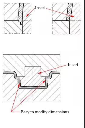
(3) Easy to resize and repair
For molded parts, where size may change, combined structure should be considered, as shown in Figure 5.4.3; for bumps and rubs that are easy to wear, inlaid structure should be adopted for strength and convenient maintenance.
(4) Ensure strength of molded parts
(5) Easy to assemble
For molded parts of mosaic structure, easy assembly is basic requirement of mold design, and errors during installation should be avoided. For a well-shaped insert or a mold with multiple inserts with same external dimensions, consideration should be given to avoiding dislocation installation of insert and turning installation of same insert during design. Method often used is asymmetrical fastening or positioning of inserts, as shown in Figure 5.4.4b.
In Figure 5.4.4a, fastening positions are symmetrical, which is easy to cause misalignment installation of insert 1 and insert 2, and same insert is also easy to turn to install. In Figure 5.4.4b, fastening positions of each insert are layout asymmetrically, fastening positions of insert 1 and insert 2 are not same, so as to avoid misalignment installation and turning installation of same insert. In addition, in order to avoid dislocation installation, asymmetrical layout of positioning pins can also be used.
In Figure 5.4.4a, fastening positions are symmetrical, which is easy to cause misalignment installation of insert 1 and insert 2, and same insert is also easy to turn to install. In Figure 5.4.4b, fastening positions of each insert are layout asymmetrically, fastening positions of insert 1 and insert 2 are not same, so as to avoid misalignment installation and turning installation of same insert. In addition, in order to avoid dislocation installation, asymmetrical layout of positioning pins can also be used.

(6) Cannot affect appearance
In design of molded parts, not only process requirements must be considered, but also appearance requirements of plastic parts must be ensured. Whether part allows clamping line to exist is prerequisite for determining whether insert can be made. If clamping line is allowed, mosaic structure should be considered, otherwise, only other structural forms can be adopted. In Figure 5.4.5, if surface of part allows existence of clamping lines, inlay structure can be used to facilitate processing; in Figure 5.4.6, front surface of part does not allow existence of clamping lines. In order to facilitate processing or other purposes, clamp position is moved to side wall, thereby adopting mosaic structure. In Figure 5.4.7, when arc is not allowed to clamp wire, change insert structure and move clamping position to inner wall.

(7) Comprehensive consideration of mold cooling.
After molded parts adopt mosaic structure, if local cooling is difficult, other cooling methods or overall structure should be considered.
Recommended
Related
- Motor Support Plate Die-Casting Process Design and Optimization07-29
- A Comprehensive Guide to Hot Runner Thermostats in Injection Molds: How Experts Choose, Use, and Rep07-29
- Hydraulic Cylinder Core Pulling Design Considerations07-28
- Interpreting Four Key Parameters of Injection Molding and Their Impact on Product Quality07-28
- Taking silicone oil fan clutch housing as an example, let's discuss analytical logic of leakage07-27