
Circular shell mold flow analysis and injection mold design
Time:2020-07-06 09:07:26 / Popularity: / Source:
Side core-pulling structure is mostly used in injection mold design to form side holes or recessed parts of plastic parts. Forced demoulding of plastic parts cannot be achieved when mold is opened, a lateral moving device in a direction different from mold-opening direction is used to drive core pulling structure and separate from plastic part to ensure integrity and quality of plastic part demoulding. When injection mold is opened to complete side core pulling action, molding component, motion component, transmission component, locking component, and limit component are required to closely cooperate. Therefore, increase in the number of injection mold side core pulling structural parts will increase complexity of mold structure design and manufacturing. Design of an injection mold with 7 side core pulling structures is introduced. Combining analysis and calculation of mold flow, design scheme of injection mold is described.
1 Molding process analysis
Plastic part is a circular shell structure with a basically symmetrical shape. As shown in Figure 1, wall thickness is 2mm. Side walls are distributed with seven directions and different sizes of holes. There are a lot of reinforcing ribs at the bottom, as main support structure for parts, plastic parts require smooth outer surface.

(A) Top view

(B) bottom view
Figure 1 Plastic parts
According to function and structural requirements of plastic parts, ABS plastic injection molding is used. Mold is designed with 2 cavity structures. During injection molding, plastic parts are required to have no pores and weld marks, and are produced in medium batches.
2 Mold flow analysis
Mold flow analysis software CAE is used to analyze molding of plastic parts. Software simulates injection molding process of plastic parts to obtain flow form of melt. Through mold cavity, mold temperature and pressure values are checked to provide designer with reference values. Simulation can analyze temperature change, pressure, welding mark and air cavity distribution of plastic parts to be molded in mold cavity. Calculation results of mold flow analysis can predict problems that may occur in actual filling process, so that mold structure can be modified in time when design is summarized. Use of CAE software can improve molding quality of plastic parts, avoid problems in later production and manufacturing of molds, save time and costs.
01 Gate determination
Moldflow/MPA provides gate calculation data, click Moldflow main menu Analysis→Set Analysis Sequence in system pop-up dialog box, select Gate Location, click OK, system will automatically analyze gate results, gate position calculated by mold flow analysis is shown in Figure 2. After analysis, dark area in Figure 2 is optimal gate position.

Fig. 2 Gate position calculated by mold flow analysis
According to actual experience of injection molding of ABS materials, combined with consideration of injection method and overall structure of mold, injection point cannot affect appearance of plastic part and cannot interfere with mold part; if direct injection is used, it is easy to cause shear marks on outer surface of plastic part. In the end, latent gate injection method is used to avoid leaving traces on the surface of plastic part during molding. After molding, gate condensate will automatically break off with plastic part when it is pushed out, which is conducive to automated operation and improves production efficiency. Since plastic part is composed of two inner covers, it adopts a 2 cavity structure and is symmetrically distributed. Runner is set between two plastic parts. Time for melt to fill cavity during injection is about same. At the same time, the nearest rib is selected to connect runner and plastic part. Fig. 2 Gate position calculated by mold flow analysis.
02 Fill analysis

(A) Fill analysis

(B) Pressure loss analysis

(C) Flow front temperature

(D) Analysis of weld line

(E) Cavitation
Figure 3 Moldflow analysis
Filling time refers to flow time of melt from gate to each position of cavity during injection process. As shown in Figure 3(a), filling is started at the earliest around gate of cavity, and bottom of outer contour of plastic part to be molded is filled last. The total filling time is 1.17s. As can be seen from Figure 3(a), flow state of melt in mold cavity at all times. Under balanced flow state, each branch flow will reach end of cavity at the same time, unbalanced state will cause molded plastic parts to warp or weld marks.
03 Pressure loss analysis
Pressure loss in melt filling mainly comes from pressure loss of runner system and pressure loss inside mold cavity, which is closely related to design of mold structure, such as selection of injection point location, size of injection point size, whether exhaust structure and design of cooling system are reasonable, etc., Pressure loss analysis is shown in Figure 3(b). It can be seen from Figure 3(b) that required injection pressure of mold is 31.75MPa, and cavity pressure loss is large, but in actual production, injection pressure of injection molding machine is greater than theoretical pressure, about 50MPa. From pressure loss analysis, it can be seen that pressure gradient of cavity is relatively uniform, sides of feed are symmetrical and uniform, and there will be no molding quality defects such as stagnation and overflow.
04 Flow front temperature
Melt flow front temperature is distribution of flow front temperature of polymer melt during filling process. Figure 3(c) shows temperature at the center of cross-section at each infusion time point, with little change. Flow front temperature can be analyzed in conjunction with weld line (Figure 3(d)). The higher melt temperature when weld line is formed, the better quality of weld line; In the melt cross section, the first place where weld line is formed is center of cross section. If temperature of flow front is higher, strength of weld line is higher; if temperature of flow front drops sharply, close to solidification temperature, it prevents melt from entering this area.
05 Welding mark analysis
Welding trace is a linear trace, which refers to contact part of more than two strands of melt. Because melt will lose heat through runner, two strands of melt cannot be welded well after temperature drops, resulting in weld marks, strip-shaped position in Fig. 3(d) is distribution position of weld line. In order to reduce possibility of welding marks, mold adopts a single gate, and structure of hot runner gating system will not affect melt filling speed.
06 Cavitation
Air cavities are mainly distributed on boundaries of plastic parts, which are caused by unbalanced flow paths or stagnant melts. Air cavities can cause warping of molded plastic parts, scorching at local locations, etc., causing local deformation of plastic parts, incomplete filling, and presence of air holes inside. Distribution of cavitation positions of plastic parts is shown in Figure 3(e). White dots in Figure 3(e) represent cavitation; in subsequent mold design, consideration will be given to reasonable setting of vent holes at the junction of melt, parting surface, insert and mold wall, push rod and mold slider, to maximize elimination of cavitation .
3 Mold structure design

Figure 4 Core structure of injection mold
Mold design is completed by Pro/E. Overall structure of mold is retrieved from EMX plug-in. Core structure of mold is shown in Figure 4. Design of mold parts depends on shape and size of plastic parts. Side walls of plastic parts are distributed with 7 holes with different sizes. Positions of mold parts are reasonably arranged inlater mold design process to avoid interference of mold parts in later mold opening process. .
Core cavity adopts a mosaic structure, which is convenient for manufacture and assembly of mold parts. Because mold parts are in contact with melt, materials with good molding properties should be selected. During injection process, melt is in contact with core and cavity plate to ensure quality of surface of plastic part, and to avoid warping or scorching of plastic part during molding process.
Mold adopts latent gate injection molding. During design, gate is placed on reinforcing rib on lower surface of plastic part, and no trace will be left on the surface during injection molding. After molding, when push rod is pushed out, gate condensate will automatically break off with plastic parts, which is conducive to automated production and improves production efficiency.
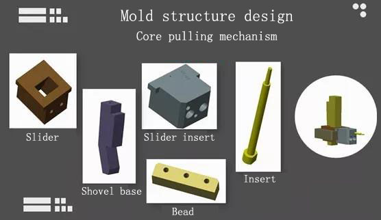
Figure 5 Core pulling structure
Mold is composed of core pulling structures in 7 directions. Each core pulling structure is composed of a wedge block and a slider insert. As shown in Figure 5, side core pulling structure in each direction will be in a different position, and position of small core should be layout reasonably. When designing mold, size and length of core should be reduced as much as possible. Due to small back hole of plastic part and short core pulling distance, small wedge block is used to replace inclined guide column, which not only saves mold space, ensures that parts will not interfere when core is pulled in all directions. Figure 5 core pulling structure
Guide mechanism of mold is mainly composed of a straight guide column guide sleeve, general guide column guide sleeve can meet use requirements of mold. Pushing mechanism chooses ordinary straight pusher to push, and pusher is used to push around ribs. At the same time, pay attention to layout of pushing position, and force should be as uniform as possible to avoid phenomenon of pulling plastic parts. Cooling system is equipped with cooling water channels in both fixed and movable mold. Cooling water channels are layout around core, which can cool down in time, make plastic parts cool quickly, and shorten molding time.
Mold structure is shown in Figure 6, and mold opening sequence is divided into two steps: Step 1: Fixed mold seat plate is separated from fixed mold plate, fixed mold seat plate drives movement of square guide column to drive side core pulling out; Step 2: Moving mold part moves, push plate acts on push rod to push out plastic parts. After pushing action is completed, moving mold part is reset. The spring on the reset lever pushes the push plate to reset. Under push of moving mold, fixed mold plate and fixed mold seat plate are closed, and then fixed mold plate and movable mold plate are closed, waiting for next injection cycle.
Recommended
Related
- Motor Support Plate Die-Casting Process Design and Optimization07-29
- A Comprehensive Guide to Hot Runner Thermostats in Injection Molds: How Experts Choose, Use, and Rep07-29
- Hydraulic Cylinder Core Pulling Design Considerations07-28
- Interpreting Four Key Parameters of Injection Molding and Their Impact on Product Quality07-28
- Taking silicone oil fan clutch housing as an example, let's discuss analytical logic of leakage07-27