
How to solve three major factors that lead to warpage of plastic parts
Time:2020-04-27 11:02:51 / Popularity: / Source:
Warpage of plastic parts means that shape of injection product deviates from shape of mold cavity. It is a common defect in injection product and has a great influence on the appearance quality and performance of injection products. With development of plastics industry, degree of warpage deformation is one of important indicators for evaluating quality of plastic parts, it has also received more and more attention from mold designers and product users. There are many factors that cause uneven shrinkage of plastic parts, including product structure, mold design, raw material performance and molding process parameters. With continuous development of mold industry, role of CAD / CAE / CAM technology in mold design and product design is becoming more and more obvious. As mainstream analysis software in injection molding, Moldflow has completely changed traditional design mode of over-relying on experience of designers during mold design process to find problem through continuous trial and error., Moldflow software can simulate and analyze filling, flow, shrinkage, cooling, plastic warpage of melt during injection process, allowing designers to find solutions and purposely make design improvements, which is of great significance to shorten design cycle, improve efficiency, ensure product quality and reduce costs.
1 T-shaped slender base problem overview

Fig.1 Base with warpage deformation
Base shown in Figure 1 is 133.5mm long and 12.5mm wide. It is a slender plastic part. Material grade is Duranex 3300 PBT, which is 30% glass fiber reinforced crystalline plastic resin. After injection molding of pedestal, warpage is severely deformed. As can be seen from Figure 1, there is a clear arc-shaped arc in the middle of pedestal placed on horizontal surface. Entire base is warped in a bow shape, and total deformation is measured to be about 0.35mm, which does not meet design and use requirements.
2 Analysis of cause of warpage of plastic parts

Figure 2 Wall thickness of each part of base

Figure 3 Schematic diagram of regional contraction
From perspective of injection molding, cause of warpage in plastic parts is uneven shrinkage, which is mainly manifested in following three points: ① uneven shrinkage in different areas on plastic part; ② uneven shrinkage in thickness direction; ③ shrinkage is uneven in parallel and vertical directions of material molecular orientation. Maximum wall thickness of plastic part is 0.7mm, minimum is 0.49mm, maximum wall thickness (without small holes) is 5.02mm, and minimum is 2.73mm, as shown in Figure 2. According to area shrinkage theory, this uneven shrinkage is caused by different crystallinity and different volume shrinkage. Wall thickness of pedestal step is greater than the rest, side wall thickness is much greater than hole spacing wall thickness, as shown in Figure 3. Uneven wall thickness of pedestal will produce different cooling rates. During cooling and shrinking process of molten plastic, due to thicker wall thickness of pedestal step and side wall, heat contained in pedestal step and side wall is larger than the rest, so plastics here is fully crystallized, shrinkage and cooling rate are slower than thin-walled parts. This uneven shrinkage and cooling causes base to warp and deform.
01 Moldflow simulation flow analysis

Figure 4 Flow analysis results
Figure 4 shows results of Moldflow simulation flow analysis. It can be seen from Figure 4 that after melt enters cavity, it exhibits a distinct non-uniform flow state. After thinner wall part of melt enters mold cavity, due to greater resistance of core in mold, flow is slow, While melt with thicker wall thickness is less resistant due to absence of mold core, its flow speed is much greater than that of thin wall. Unbalanced flow is one of reasons for warpage of plastic.
02 Moldflow warpage analysis

Figure 5 Results of warpage analysis

Figure 6 Fiber orientation analysis results
Results of Moldflow warpage analysis are shown in Figure 5. It can be seen that maximum theoretical deformation amount of plastic part in Z direction is about 0.4mm. Both ends are more warped than middle part, whole shows a serious warpage deformation, and deformation trend is consistent with actual object. Through further analysis of fiber orientation (see Figure 6), fiber orientation of wall thickness of base is inconsistent at the end and middle. According to theory of warpage, uneven orientation of molecules is one of reasons for warpage of plastic parts.
3 improve proposals

Figure 7 Optimized plastic parts structure
According to analysis results of Moldflow, it can be judged that uneven wall thickness, uneven flow and uneven molecular orientation are three main factors of warpage deformation of base. According to Moldflow's modification plan, appropriate modification of wall thickness of plastic part area can reduce degree of warpage. Without affecting structure and performance of base, optimized structure of plastic parts is shown in Figure 7. Twenty-two 7.6mm * 0.6mm * 3.4mm process grooves were added uniformly and symmetrically in wall thickness of base. Thicker parts were hollowed out to make wall thickness uniform, corresponding inserts were added to mold structure to ensure thicker part of melt flows slowly after entering cavity, so that flow becomes balanced.
4 Improvement scheme verification
01 Moldflow simulation flow analysis

Figure 8 Flow analysis results
Figure 8 shows Moldflow simulation flow analysis results after structure of plastic part is improved. From Figure 8, it can be clearly seen that melt flow speed of thick wall part and thin wall part is greatly improved compared with that before optimized structure. Flow rate of melt in thin part and thick part of wall tend to be basically same. After melt in wall thickness part of optimized plastic structure part enters mold cavity, same as core's obstruction to melt, melt must bypass process insert to continue to flow forward, melt flow speed is slowed, and melt flow rate is close to thin wall part, indicating that process tank plays a role in slowing melt flow rate and balancing flow.
02 Moldflow warpage analysis

Figure 9 Flow analysis results

Figure 10 Fiber orientation analysis results
Using Moldflow to analyze warpage of plastic parts, results are shown in Figure 9. From Figure 9 we can see that theoretical maximum warpage of plastic parts has changed from original 0.41mm to current 0.19mm, a decrease of 0.22 mm. Part with large warpage is basically concentrated at both ends of base, and the overall deformation is greatly improved compared with previous one. From results of fiber orientation analysis (see Figure 10), fiber orientation of bottom wall thickness portion has been greatly improved compared with before, and wall thickness portion tends to be consistent, indicating that addition of process grooves helps to reduce warpage and make shrinkage of plastic parts tend to be balanced.
03 Physical processing effect
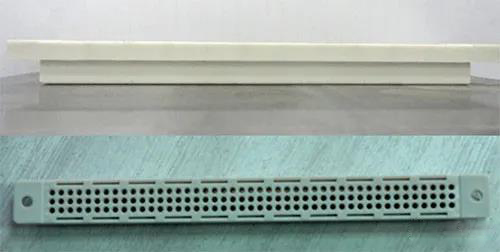
Figure 11 Finalized prototype
After optimized structural design, injection molded plastic parts are shown in Figure 11. It can be seen that plastic parts are basically flat with reference surface, problem of overall warpage and deformation can be solved. Positions and sizes of holes at both ends were measured to meet design requirements, and use requirements were met after trial installation.
Last article:109 acceptance criteria for molding
Next article:Principle of using mold ejector pin!
Recommended
Related
- Motor Support Plate Die-Casting Process Design and Optimization07-29
- A Comprehensive Guide to Hot Runner Thermostats in Injection Molds: How Experts Choose, Use, and Rep07-29
- Hydraulic Cylinder Core Pulling Design Considerations07-28
- Interpreting Four Key Parameters of Injection Molding and Their Impact on Product Quality07-28
- Taking silicone oil fan clutch housing as an example, let's discuss analytical logic of leakage07-27