
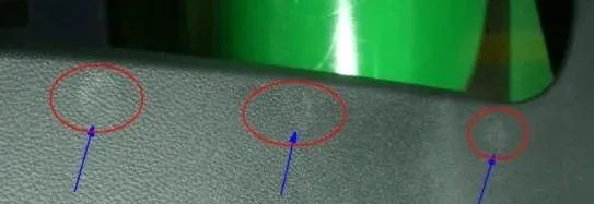
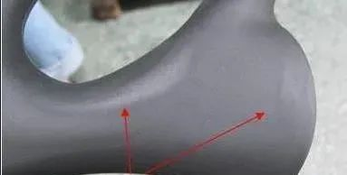
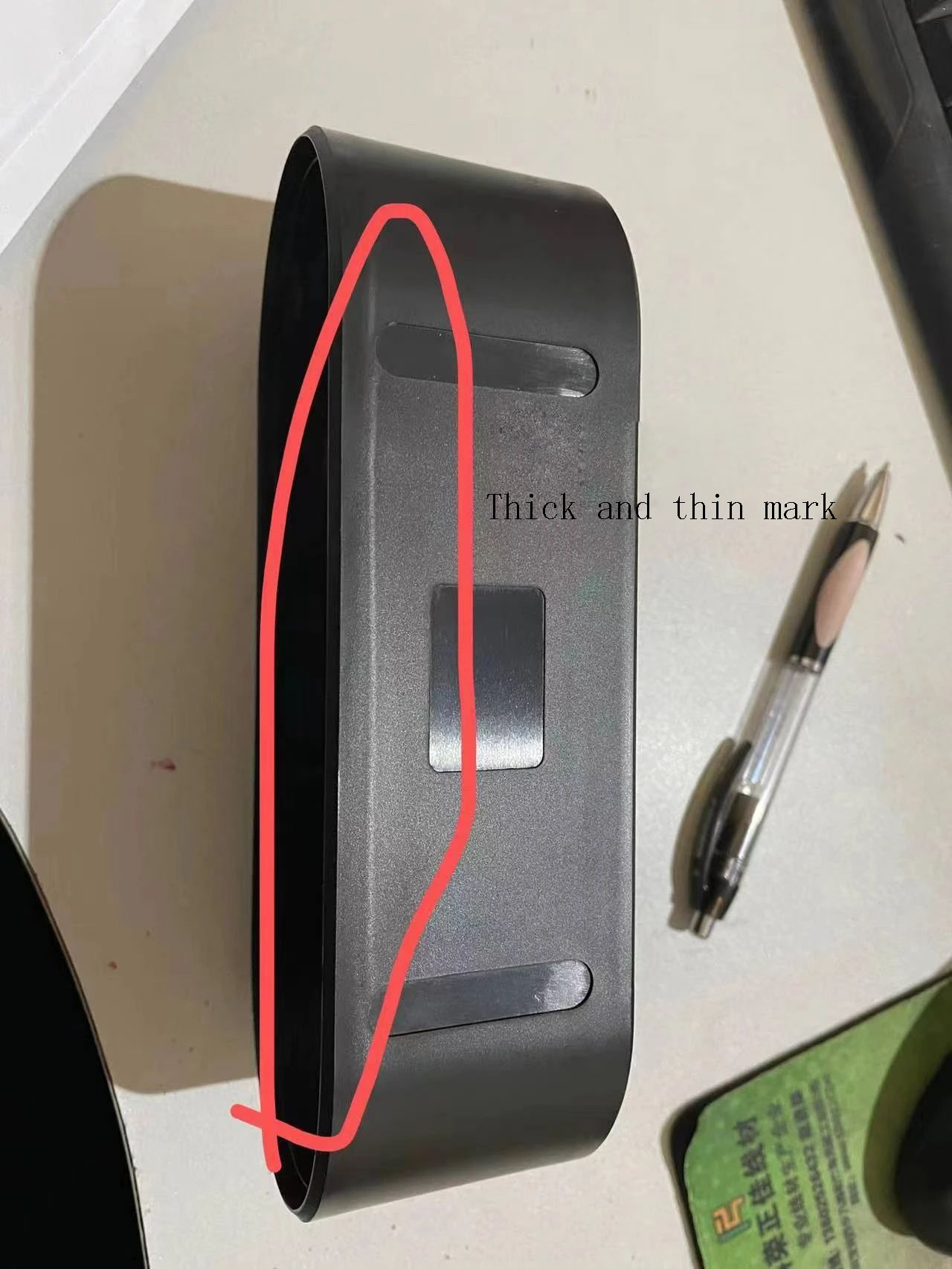
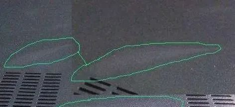
How to solve stress marks (ejector pin marks, white edges, thick and thin marks)?
Time:2023-12-17 20:50:55 / Popularity: / Source:
On plastic products, especially those whose raw materials are ABS, PP, and PC, we often see shiny stress marks on the surface of product, such as ejector pin stress marks, insertion stress marks, and flesh thickness difference stress marks.
These apparently shiny and white marks are result of internal stress, which is nothing more than orientation stress and cooling shrinkage stress. Irregular stress marks near gate are caused by typical orientation stress, while thickness difference is joint result of orientation and shrinkage stress. There are more factors that cause stress marks of ejector pins and oblique pins.
Under normal circumstances, as holding pressure and time increase, the first are stress marks of thickness difference, stress marks of ejector pin oblique pin, then stress marks of thickness difference, and finally irregular stress marks near gate (it will look white and shiny when viewed from side). Of course, this also depends on specific structure of product and gating position.
Therefore, when these stress marks appear, it is most important to reduce holding pressure and holding time. Once you understand this, you can start from here to modify product design and mold design more effectively than molding adjustments.
A. Mechanism of internal stress generation
Plastic internal stress refers to an internal stress generated during plastic melting process due to factors such as orientation of macromolecular chains and cooling shrinkage.
Essence of internal stress is unbalanced conformation formed by macromolecular chain during melting process. This unbalanced conformation cannot immediately return to equilibrium conformation that is compatible with environmental conditions when cooling and solidifying. Essence of this unbalanced conformation is a reversible high elastic deformation, and frozen high elastic deformation is usually stored in plastic product in the form of potential energy. Under appropriate conditions, this forced unstable conformation will transform into a free stable conformation, potential energy will be converted into kinetic energy and released.
When forces and entanglements between macromolecular chains cannot withstand this kinetic energy, internal stress balance will be destroyed, plastic products will produce stress cracking and warping deformation.

B. Causes of internal stress in plastics
(1) Orientation internal stress
Orientation internal stress is an internal stress generated by frozen conformation of macromolecular chains arranged along flow direction during flow filling and pressure maintaining process of plastic melt.
Detailed process of generating orientation stress is as follows: viscosity of outer melt increases due to rapid cooling rate of melt near runner wall. As a result, flow rate of melt in core layer of cavity is much higher than flow rate in the surface layer, resulting in shear stress between internal layers of melt, resulting in orientation along flow direction.
Thawing of oriented macromolecular chains in plastic products means that there is unrelaxed reversible high elastic deformation. Therefore, orientation stress is internal force that macromolecular chains strive to transition from oriented conformation to non-oriented conformation. Heat treatment can reduce or eliminate orientation stress in plastic products.
Oriented internal stress distribution of plastic products becomes smaller and smaller from surface layer to inner layer of product, and changes in a parabola.
(2) Cooling internal stress
Cooling internal stress is an internal stress caused by uneven shrinkage of plastic products during cooling and shaping during melting process. Especially for thick-walled plastic products, outer layer of plastic product cools, solidifies and shrinks first, and inner layer may still be hot melt. This will cause core layer to limit contraction of surface layer, causing core layer to be in a state of compressive stress and surface layer to be in a state of tensile stress.
Distribution of internal stress during cooling of plastic products becomes larger and larger from surface layer to inner layer of product, and also changes in a parabola.
In addition, for plastic products with metal inserts, because thermal expansion coefficients of metal and plastic are quite different, it is easy to cause uneven internal stress due to shrinkage.
In addition to above two important internal stresses, there are also following internal stresses: For crystalline plastic products, internal stresses will also occur due to differences in crystal structure and crystallinity of each part of product. In addition, there are structural internal stresses and demoulding internal stresses, etc., but proportion of internal stresses is very small.

C. Factors affecting internal stress of plastics
(1) Rigidity of molecular chain
The greater rigidity of molecular chain, the higher melt viscosity. Polymer molecular chain has poor mobility, so it has poor recovery from reversible high elastic deformation and is prone to residual internal stress. For example, some polymers containing benzene rings in molecular chain, such as PC, PPO, PPS, etc., have relatively large internal stress in their corresponding products.
(2) Polarity of molecular chain
The greater polarity of a molecular chain, the greater force of mutual attraction between molecules, which makes it more difficult for molecules to move between each other and reduces degree of recovery of reversible elastic deformation, resulting in large residual internal stress. For example, some types of plastics containing polar groups such as carbonyl, ester, and nitrile groups in their molecular chains have relatively large internal stresses in their corresponding products.
(3) Steric hindrance effect of substituting groups
The larger volume of macromolecular side substituent group, free movement of macromolecular chain will be hindered, resulting in increased residual internal stress. For example, phenyl group of polystyrene substituent group is larger, so internal stress of polystyrene product is larger.
D. Control of plastic internal stress reduction and evacuation
(1) Raw material formula design
① Select resins with large molecular weight and narrow molecular weight distribution
The larger molecular weight of polymer, the greater force and entanglement between macromolecular chains, and products have stronger resistance to stress cracking; the wider molecular weight distribution of polymer, the larger low molecular weight components, which will easily cause microscopic tears first, resulting in stress concentration and cracking of product.
②Choose resin with low impurity content
Impurities in polymer are equal to stress concentrators and will reduce original strength of plastic. Impurity content should be reduced to a minimum.
③Blending modification
Resins prone to stress cracking can be blended with other suitable resins to reduce presence of internal stress.
For example, by mixing an appropriate amount of PS into PC, PS is dispersed in PC continuous phase in an approximate bead shape, which can alleviate internal stress by dispersing along spherical surface and inhibit expansion of cracks, thereby achieving purpose of reducing internal stress. For another example, if an appropriate amount of PE is mixed into PC, a closed cavitation zone can be formed on outer edge of PE pellet, which can also appropriately reduce internal stress.
For example, by mixing an appropriate amount of PS into PC, PS is dispersed in PC continuous phase in an approximate bead shape, which can alleviate internal stress by dispersing along spherical surface and inhibit expansion of cracks, thereby achieving purpose of reducing internal stress. For another example, if an appropriate amount of PE is mixed into PC, a closed cavitation zone can be formed on outer edge of PE pellet, which can also appropriately reduce internal stress.
④ Strengthen modification
Reinforcement modification with reinforcing fibers can reduce internal stress of product. This is because fibers are entangled with many macromolecular chains, thereby improving stress cracking ability. For example, stress cracking resistance of 30% GFPC is as much as 6 times higher than that of pure PC.
⑤ Nucleation modification
Adding appropriate nucleating agents to crystalline plastics can form many small spherulites in products, reducing internal stress and dispersing it.
(2) Control of molding processing conditions
In molding process of plastic products, any molding factors that can reduce orientation of polymer molecules in product may reduce orientation stress; any process conditions that can uniformly cool polymer in product can reduce cooling internal stress; any processing method that helps plastic products to demould can help reduce internal stress of demoulding.
Processing conditions that have a greater impact on internal stress mainly include following:
Processing conditions that have a greater impact on internal stress mainly include following:
①Barrel temperature
A higher barrel temperature is conducive to reduction of orientation stress. This is because at a higher barrel temperature, melt is plasticized evenly, viscosity decreases, and fluidity increases. When melt fills cavity, molecular orientation effect is small, so orientation stress is small. At a lower barrel temperature, melt viscosity is higher, molecular orientation is more during mold filling process, residual internal stress after cooling and setting is larger. However, it is not good if barrel temperature is too high. Too high a temperature can easily lead to insufficient cooling and deformation during demolding. Although orientation stress is reduced, cooling stress and demoulding stress are increased.
②Mold temperature
Temperature of mold has a great influence on orientation internal stress and cooling internal stress. On the one hand, if mold temperature is too low, cooling will be accelerated, which may lead to uneven cooling and cause large differences in shrinkage, thereby increasing internal stress of cooling; on the other hand, if mold temperature is too low, melt will enter mold. Temperature decreases faster and melt viscosity increases rapidly, causing mold to be filled under high viscosity and degree of orientation stress to be formed is significantly increased.
Mold temperature has a great influence on plastic crystallization. The higher mold temperature, the more conducive to tight packing of crystal grains, which reduces or eliminates shortcomings within crystal, thereby reducing internal stress.
In addition, for plastic products of different thicknesses, mold temperature requirements are different. For thick-walled products, mold temperature should be appropriately higher.
③Injection pressure
Injection pressure is high, shearing force experienced during melt filling process is large, and orientation stress is also large. Therefore, in order to reduce orientation stress and demoulding stress, injection molding pressure should be appropriately reduced. .
④Holding pressure
Impact of holding pressure on internal stress of plastic products is greater than impact of injection pressure. During pressure holding stage, as melt temperature decreases, melt viscosity increases rapidly. If high pressure is applied at this time, it will inevitably lead to forced orientation of molecular chains, resulting in greater orientation stress.
⑤Injection speed
The faster injection speed, the easier it is to increase orientation of molecular chain, thereby causing greater orientation stress. However, if injection speed is too low, after plastic melt enters mold cavity, it may stratify successively to form melt marks, produce stress concentration lines, and easily cause stress cracking. Therefore, injection speed should be moderate. It is best to use variable speed injection and stop filling mold when speed gradually decreases.
⑥Pressure holding time
The longer holding time will increase shearing effect of plastic melt, resulting in greater elastic deformation and freezing of more orientation stresses. Therefore, orientation stress increases significantly with extension of holding time and increase of feeding amount.
⑦Mold opening residual pressure
Injection pressure and pressure holding time should be adjusted appropriately to make residual pressure in mold close to atmospheric pressure when opening mold, thereby avoiding greater internal stress during demoulding.
⑶Design of plastic products
①Shape and size of plastic products
When designing plastic products, in order to effectively disperse internal stress, following principles should be followed: shape of product should be as consistent as possible, avoiding sharp angles, right angles, gaps and sudden expansion or contraction.
Edges of plastic products should be designed with rounded corners, where inner fillet radius should be greater than 70% of thickness of thinner of the two adjacent walls; outer fillet radius should be determined according to shape of product.
For parts with large wall thickness differences, cooling internal stress and orientation internal stress are likely to occur due to different cooling rates. Therefore, parts should be designed with wall thickness as uniform as possible. If wall thickness must be uneven, a gradual transition of different wall thicknesses must be made.
② Reasonable design of metal inserts
Thermal expansion coefficients of plastics and metals differ by 5 to 10 times. Therefore, when plastic products with metal inserts are cooled, the two shrink to different degrees. Because compression of plastic is relatively large, it tightly hugs metal insert. Surrounding plastic inner layer is subject to compressive stress, while outer layer is subject to tensile stress, resulting in stress concentration.
When designing inserts in detail, following points should be paid attention to to help reduce or eliminate internal stress:
a. Try to choose plastic parts as inserts.
b. Try to choose metal materials that have a small thermal expansion coefficient difference with plastics as insert materials, such as aluminum, aluminum alloys and copper.
c. Coating a layer of rubber or polyurethane elastic buffer layer on metal insert and ensuring that coating layer does not melt during molding can reduce shrinkage difference between the two.
d. Surface degreasing of metal inserts can prevent grease from accelerating stress cracking of products.
e. Metal inserts are properly preheated.
f. Thickness of plastic around metal insert should be sufficient. For example, if outer diameter of insert is D and plastic thickness around insert is h, then for aluminum inserts, plastic thickness h ≥ 0.8 D; for copper inserts, plastic thickness h ≥ 0.9 D.
g. Metal inserts should be designed in a smooth shape, preferably with delicate knurling patterns.
③Design of holes in plastic products
Shape, number and location of holes on plastic products will have a great impact on degree of internal stress concentration. To avoid stress cracking, avoid opening prismatic, rectangular, square or polygonal holes in plastic products. Circular holes should be opened as much as possible, with oval holes having the best effect, and long axis of oval hole should be parallel to direction of external force.
If you want to open a round hole, you can add process holes of equal diameter, and make central connecting line of two adjacent round holes parallel to direction of external force, so that you can get an effect similar to an elliptical hole; there is another method, that is, open symmetrical slots around circular hole to disperse internal stress.
If you want to open a round hole, you can add process holes of equal diameter, and make central connecting line of two adjacent round holes parallel to direction of external force, so that you can get an effect similar to an elliptical hole; there is another method, that is, open symmetrical slots around circular hole to disperse internal stress.
⑷Design of plastic mold
When designing plastic molds, gating system and cooling system have a greater impact on internal stress of plastic products. Following points should be paid attention to in specific design.
①Gate size
A gate that is too large will require a longer pressure-holding and replenishing time. Replenishing flow during cooling process will definitely freeze more orientation stresses, especially when filling cold materials, which will cause great internal stress near gate.
Appropriately reducing gate size can shorten time of pressure maintaining and replenishing materials, reduce pressure in mold when gate is solidified and sealed, thereby reducing orientation stress. However, gates that are too small will extend mold filling time and cause product shortages.
Appropriately reducing gate size can shorten time of pressure maintaining and replenishing materials, reduce pressure in mold when gate is solidified and sealed, thereby reducing orientation stress. However, gates that are too small will extend mold filling time and cause product shortages.
②Location of gate
Position of gate determines flow situation, flow distance and flow direction of plastic melt in mold cavity. When gate is located at the thickest part of product wall, injection pressure, holding pressure and holding time can be appropriately reduced to help reduce orientation stress. When gate is located in a thin-walled area, wall thickness at gate should be appropriately increased to reduce orientation stress near gate.
The longer flow distance of melt in mold cavity, the greater probability of generating orientation stress. For this reason, for plastic parts with thick walls, long processes and large areas, multiple gates should be appropriately distributed, which can effectively reduce orientation stress and prevent warping deformation.
In addition, because area around gate is prone to internal stress, an ear-protection gate can be installed near gate to cause internal stress to occur in ear-protection. Removing ear protection with large internal stress after demoulding can reduce internal stress in plastic product.
③Design of runner
Designing a short and thick runner can reduce pressure loss and temperature drop of melt, correspondingly reduce injection pressure and cooling speed, thereby reducing orientation stress and cooling pressure.
④ Design of cooling system
1. Distribution of cooling water channels should be reasonable, so that areas near gate, away from gate, thick walls, thin walls are cooled evenly and slowly, thereby reducing internal stress.
2. Where there are stress marks, water channels need to be added to increase local high temperatures.
2. Where there are stress marks, water channels need to be added to increase local high temperatures.
⑤Design of ejection system
It is necessary to design an appropriate demoulding taper, a high core smoothness and a large ejection area to prevent demoulding stress caused by forced demoulding.
E. Detection method of plastic stress
1. Solution method
⑴Acetic acid immersion
Acetic acid (CH3COOH) used must be more than 95% acetic acid and number of repeated uses must not exceed 10 tests.
① Surface stress test: Pour acetic acid (glacial acetic acid) into glassware, and completely immerse product in acetic acid for 30 seconds. After 30 seconds, use a clamp to take out sample and immediately rinse it with clean water (tap water is sufficient). Check whether there are any whitening or cracks on the surface of sample. Judgment: There should be no cracking, and a slight whitening on the surface is allowed.
② Internal stress test: Dry sample that has passed surface stress test and completely immerse it in acetic acid for 2 minutes. After 2 minutes, take out sample and rinse it immediately with clean water (tap water is sufficient), and inspect sample for whitening and cracks. Judgment: There must be no breakage. Slight cracks and surface whitening on insert are permitted.
⑵Methyl ethyl ketone + acetone immersion method: Completely immerse the whole machine in a 1:1 mixture of methyl ethyl ketone + acetone at 21 degrees Celsius, take it out and spin dry immediately, and check according to above method.
Principle: Based on phenomenon of medium stress rupture, that is, after solvent molecules penetrate into macromolecules of resin, interaction force between molecules is reduced. In areas with large internal stress, force between molecules was originally weakened before immersion. After immersion in solution, these weakened areas are further weakened, causing cracking. Areas with small internal stress will not crack in a short time. Therefore, size and location of internal stress of plated part can be determined from the time and degree of surface cracking of parts to be plated, and thus whether plastic parts are electroplated.
2.Instrumental method
Use polarized light to illuminate plastic parts and analyze intensity of internal stress depending on number of colored light bands. It is only suitable for transparent parts. Equipment required for polarization method is expensive, operation is complex, and accuracy is not high. Since change of part before and after treatment is not obvious, light bands appearing on spectral band are not necessarily affected by internal stress. For example, ripples on the surface of part will also affect inspection results. However, this method has no impact on performance of parts. It is a non-destructive test, inspected parts can continue to be electroplated and used.
3. Sudden temperature change method
This method is to repeatedly expose plastic parts to be plated to cold and heat, and evaluate internal stress based on the length of time cracks appear. It is suitable for all types of plastic formed parts. Equipment required for sudden temperature change method is simple, but test time is long. Plastic parts that have been repaired have been damaged and cannot be used continuously.

F. Removing stress from plastic products
Heat treatment of plastic products refers to method of keeping molded products at a certain temperature for a period of time to eliminate internal stress. Let workpiece be kept at a certain temperature for several hours to rearrange its internal components to achieve purpose of reducing or eliminating internal stress.
Heat treatment of parts can transform polymer molecules from an unbalanced conformation to a balanced conformation, so that unstable high elastic deformation of forced freezing can obtain energy for thermal relaxation, thereby reducing or basically eliminating internal stress. Commonly used heat treatment temperature is 10~20℃ higher than use temperature of parts or 5~10℃ lower than heat distortion temperature. Heat treatment time depends on plastic type, part thickness, heat treatment temperature and injection molding conditions.
Parts with individual thicknesses can be heat treated for 1 to 2 hours. As thickness of part increases, heat treatment time should be appropriately extended. Increasing heat treatment temperature and extending heat treatment time have similar effects, but effect of temperature is more obvious.
Heat treatment method is to put parts into liquid media such as water, glycerin, mineral oil, ethylene glycol and liquid paraffin, or put them into an air circulation oven to heat to a specified temperature, stay at this temperature for a certain period of time, then slowly cool to room temperature. Tests have shown that heat treatment of parts immediately after demoulding has a more obvious effect on reducing internal stress and improving performance of parts. In addition, increasing mold temperature, extending cooling time of the parts in mold, and performing thermal insulation treatment after demoulding all have similar effects to heat treatment.
Heat treatment temperatures for commonly used plastic parts
ABS plastic parts 65-------75℃ Polypropylene 80-----100℃
Chlorinated polyether 80------120℃ Polyacetal 90------120℃
Polycarbonate 110-----130℃ Polysulfone 100-----120℃
Modified polystyrene 50-----60℃ Polyphenylene ether 100-----120℃
Recommended
Related
- Motor Support Plate Die-Casting Process Design and Optimization07-29
- A Comprehensive Guide to Hot Runner Thermostats in Injection Molds: How Experts Choose, Use, and Rep07-29
- Hydraulic Cylinder Core Pulling Design Considerations07-28
- Interpreting Four Key Parameters of Injection Molding and Their Impact on Product Quality07-28
- Taking silicone oil fan clutch housing as an example, let's discuss analytical logic of leakage07-27