
11 major principles of plastic mold parts design! Must be kept in mind
Time:2023-12-11 21:15:12 / Popularity: / Source:
General principles of product structure design are basic ideas and rules to be followed in product structure design. These basic rules make product structure design more reasonable. Whether it is plastic products or hardware products, general principles of product structure design include rational selection of materials, selection of reasonable structure, simplify mold structure and cost control as much as possible.
Most plastic products are injection molded through plastic molds. When designing structure of plastic parts, general principles of product structure design should be followed. In addition, plastics also have some basic design requirements, such as material thickness, ribs, rounded corners, etc.
1 Thickness of plastic parts
Material thickness of plastic parts is the most basic design requirement for plastic parts and is closely related to outer dimensions of plastic parts. Generally speaking, products with larger outer dimensions have larger material thicknesses. Thickness of plastic parts determines strength, weight, assembly, etc. of product.(1) Thickness of plastic parts can be selected according to different materials and size of product appearance. Range is generally 0.6~6.0mm, and commonly used thickness is generally between 1.5~3.0mm.
Recommended material thickness values for commonly used plastic parts: small products refer to maximum outer dimension L<80.0mm, medium-sized products refer to maximum outer dimension L<200.0mm, and large products refer to maximum outer dimension L>200.0mm.
Unit: mm
| Plastic material | Minimum material thickness | Recommended material thickness for small products | Recommended material thickness for medium-sized products | Recommended material thickness for large products |
| ABS | 0.60 | 1.00-1.40 | 1.40-2.00 | >2.00 |
| PC | 0.60 | 0.80-1.20 | 1.20-2.00 | >2.00 |
| PMMA | 0.60 | 0.80-1.50 | 1.50-2.20 | >2.20 |
| PC+ABS | 0.60 | 0.80-1.20 | 1.20-2.00 | >2.00 |
| PP | 0.60 | 0.80-1.20 | 1.20-2.00 | >2.00 |
| PE | 0.60 | 0.80-1.20 | 1.20-2.00 | >2.00 |
| POM | 0.60 | 0.80-1.50 | 1.50-2.20 | >2.20 |
| PA | 0.60 | 0.80-1.00 | 1.00-1.60 | >1.60 |
(2) Thickness of plastic parts should be as uniform as possible, otherwise defects such as uneven filling of plastic parts, deformation, and local dents may occur.
If thickness of plastic parts is uneven due to structural requirements, transition should be gradual to avoid excessive changes in thickness, causing stress concentration or local dents that affect appearance and structural strength of product.
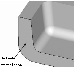
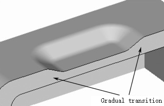
Tips: Thickness of material should not change too much. From thin to thick, it should not exceed 2.0 times, and from thick to thin, it should not be less than 0.50 times original glue level.
2 Draft angle of plastic parts
Draft angle means that plastic parts should have a certain tilt angle in direction of mold ejection, which is a necessary condition for normal mold ejection. When designing plastic parts, both appearance and inner structure must have a draft angle. Draft of mold is related to product appearance, material, product dimensions, and function of product. Design points of draft of mold mainly include following aspects.(1) For products with high requirements on product appearance, demoulding slope should be small.
(2) For products with high product precision requirements, demoulding slope should be small.
(3) For products with large dimensions, draft must be small.
(4) If plastic material contains lubricant, demoulding angle should be small.
(5) Outer surface of product is bright and demoulding slope should be appropriately small.
(6) Product has a rough appearance and demoulding angle needs to be increased.
(7) Shape of product is complex, and draft angle must be increased.
(8) When injecting plastics with poor fluidity or reinforced plastics, demoulding angle should be increased.
(9) Product material is thick and demoulding angle should be appropriately increased.
(10) Plastics with large shrinkage should use larger draft angles.
(11) Demoulding angle of plastic parts for transparent parts should be appropriately increased.
| Plastic material | Recommended draft angle |
| ABS, PA, POM, hard PVC | 40'-1°30' |
| PP, PE, soft PVC | 30’~1° |
| PC, PMMA, PC+ABS, PS | 40'~1°50' |
Tips: Plastic products should prevent appearance surface from being strained when coming out of mold. No matter what material is selected, it is recommended that demoulding angle of exterior surface should not be less than 3°.
Method for determining direction of demoulding slope is as follows:
1 Appearance of product is based on big end, and slope is obtained from small end using glue-reducing draft method.

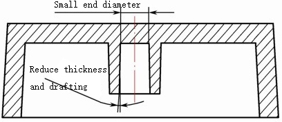
2 Inner hole is based on diameter of small end, and slope is obtained in direction of expansion using glue-reducing draft method.
3 Rib position is based on big end, and slope is obtained from small end using glue-reducing draft method.
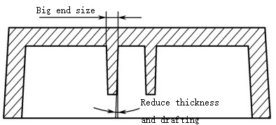
4 In special circumstances, in order to ensure uniform material thickness and smooth mold ejection, one side needs to be reduced in glue and draft, the other side needs to be added in glue and draft.

Tips: When carrying out structural design of plastic products, strictly speaking, all draft angles must be made, but in actual work, draft angles of all important mating surfaces must be made, draft angle of non-important surfaces (such as ribs) generally does not need to be made. Mold designer will make draft angle according to company's internal standards.
3 Rounded corner design of plastic parts
When designing structure of plastic parts, in order to improve strength of product, avoid stress concentration during plastic injection molding, and facilitate demoulding, transition fillets should be designed between intersections of each surface of product.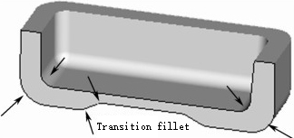
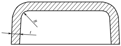
1 When there are no special requirements for product structure design, transition fillet is determined by adjacent material thickness. Inner fillet radius (R) generally ranges from 0.50 to 1.50 times material thickness (t), but minimum fillet radius shall not be less than 0.30mm
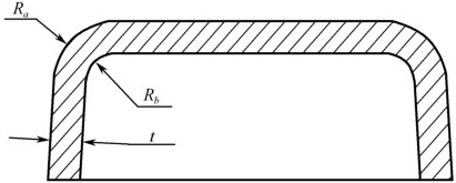
2 When designing rounded corners on inner and outer surfaces of product, material thickness should be kept uniform, as shown in Figure 4-9, Ra=Rb+t.
3 When designing structure of plastic parts, pay special attention to fact that parting surface of mold should not have rounded corners, unless product has special requirements. If parting surface has rounded corners, it will increase difficulty of mold production and leave traces of pinch lines on outer surface of product, affecting appearance.

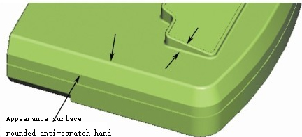
4 Sharp edges are not allowed on exposed surface and inner surface of product. If necessary, rounding should be performed. Minimum rounding radius should not be less than 0.30mm to prevent scratching fingers, especially when making toys. Special attention should be paid to structural design of similar products.
4 Reinforcement rib design for plastic parts
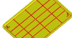
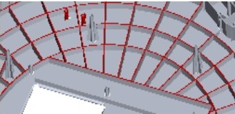
Sometimes, in order to improve strength and stiffness of plastic parts without changing material thickness, it is necessary to rationally design reinforcing ribs. Role of reinforcing ribs in plastic products is to improve strength and stiffness of plastic parts, prevent plastic parts from deforming, and also It is beneficial to flow of raw materials during injection molding.Applications of reinforcing ribs include long strip mesh reinforcing ribs and circular mesh reinforcing ribs.
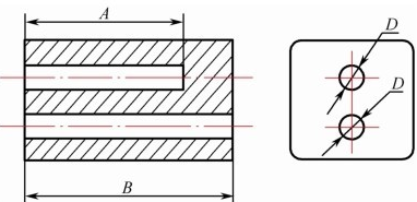
1 Design requirements for reinforcing ribs
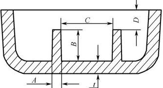
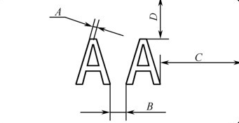
Size description:
Dimension A is thickness of large end of reinforcement, ranging from 0.4t to 0.60t. General value is 50% of material thickness.
Dimension B is height of reinforcement, which is generally required to be no more than 3t.
Dimension C is distance between two reinforcing ribs, which is generally required to be no less than 4t.
Dimension D is distance between reinforcing rib and surface of part, which is generally required to be no less than 1.00mm.
(2) Reinforcing ribs for screw columns.
If screw column is too high or needs to withstand a certain amount of force, it is necessary to design reinforcing ribs to enhance its strength. There are reinforcing ribs away from side wall screw columns, and there are also reinforcing ribs close to side wall screw columns.
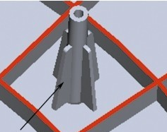
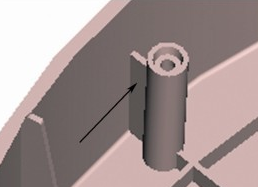
Reinforcing rib design for screw columns
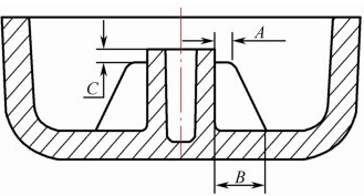
Size description:
Dimension A is plane width of upper end of stiffener, which should not be less than 0.50mm.
Dimension B is width of bottom end of reinforcing rib, and value range is 0.20 to 0.50 times height of screw column.
Dimension C is distance between reinforcing rib and top plane of screw column, which should be no less than 1.00mm.
2 If reinforcement ribs are made on support surface, reinforcement ribs should be lower than support surface to ensure that support surface is flush.

5 Support surface design of plastic parts
Support surface is bottom surface that bears weight of product. For slightly larger products, if the entire surface is used as support surface, it is not conducive to flatness of bottom, so some convex edges or bosses or bumps need to be designed for support. Height of supporting surface should be determined according to the overall dimensions of product, and certain value range is 0.30~2.00mm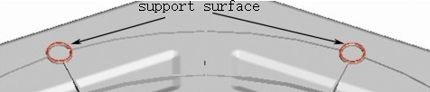
6 Design of plastic parts holes
Holes are often encountered in product structure design. There are two common types of holes, one is circular holes and the other is non-circular holes. When designing location of holes, difficulty of mold processing should be minimized without affecting strength of plastic parts.1 Design requirements for common holes
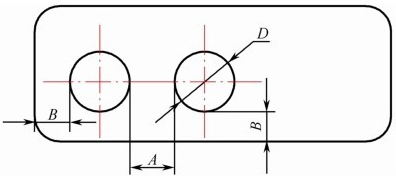
Size description:
Dimension A is distance between holes. If aperture is less than 3.00mm, it is recommended that A value is not less than D. If aperture exceeds 3.00mm, A value can be 0.70 times aperture.
Dimension B is distance between hole and edge. It is recommended that value of B is not less than D.
2 Relationship between hole diameter and hole depth
Size description:
Dimension A is depth of blind hole. It is recommended that value of A is not greater than 5D.
Dimension B is depth of through hole. It is recommended that B value is not greater than 1 0D.
Tips: Holes mentioned here do not include inner holes of screw posts.
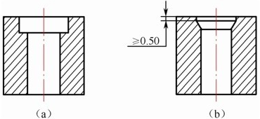
3 Screw head hole is preferably in the form shown in (a). If structure requires form shown in (b), tapered surface should be lower than end face and not less than 0.50mm to avoid cracking on hole surface.
7 Text and pattern design on plastic parts
Text and patterns on plastic products are divided into two types: convex surface and concave surface. There are generally two processing methods. Small text and patterns are obtained by etching mold, slightly larger text and patterns are obtained directly by mold processing.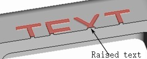

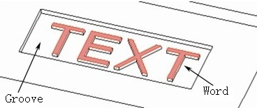
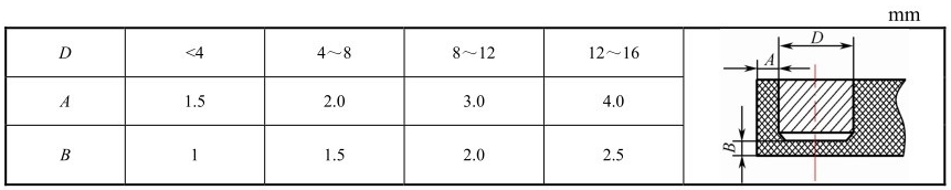
1 It is best to use convex surfaces for text and patterns on plastic products, so that they are concave on mold, making mold processing much simpler. If surface is not allowed to have protrusions due to structural requirements, you can recess area with text or patterns on the surface to a certain depth, then protrude text or pattern in groove. This not only meets structural requirements, but also facilitates mold production. It is best for convex text surface to be about 0.10mm lower than groove surface.
2 For text and patterns on plastic products, convex surface height is generally 0.15~0.30mm, depth of concave text and patterns is 0.15~0.25mm.
Size description:
Dimension A is stroke width of text, which is recommended to be no less than 0.25mm.
Dimension B is distance between two characters, which is recommended to be no less than 0.40mm.
Dimensions C and D are distance between characters and edge. It is recommended not to be less than 0.60mm.
8 Thread design on plastic parts
Threads are used to connect parts and are often used in plastic products. Threads on plastic products are somewhat different from those on hardware products. Threads on plastic products are injection molded with molds, and precision is relatively low. Thin threads are difficult to form; while threads on hardware products are machined with high precision and can process very fine threads.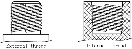
1 Thread diameter on plastic products cannot be too small, external thread diameter is not less than 3.00mm, internal thread diameter is not less than 2.00mm, and thread pitch is not less than 0.50mm

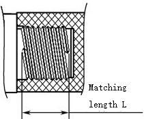
2 In order to ensure good screwing of internal and external threads, mating length of plastic thread should not be too long. It is recommended that mating length L should not be greater than 2 times thread diameter.
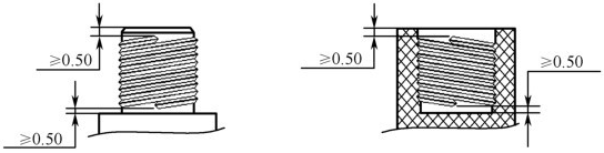
3 The first turn of plastic thread is easy to crack or trip, and in order to facilitate demolding, it is necessary to design a section of unthreaded cylindrical surface at the beginning and end of thread, with a height of not less than 0.50mm.
9 Insert design on plastic parts
Inserts on plastic parts refer to inserting parts of other materials into plastic products during injection molding and combining them with plastic products. The most commonly used inserts are metal parts, small inserts such as screws and nuts; slightly larger inserts such as stainless steel sheets used on the bottom of battery compartment in mobile phone products to reduce thickness. Main function of inserts is to improve mechanical strength and wear resistance of plastic parts. Basic requirements for designing metal inserts include following aspects.(1) Inserts require high dimensional accuracy, such as nut parts. A slightly larger difference between nut's outer dimensions and thread diameter will make it difficult to position it in mold.
(2) Strength of insert must be high enough. Due to high injection pressure of mold, parts with insufficient strength are easily damaged.
(3) Insert and plastic material must be tightly combined and cannot loosen or shake. Cylindrical inserts require a rolling grid pattern on their appearance to enhance adhesion.
(4) If insert material is a sheet material such as stainless steel sheet, in order to prevent it from falling off, more hanging platforms and cutouts should be designed on surrounding side walls to be embedded in plastic.
(5) Shape of insert is best designed to be cylindrical to facilitate placement and positioning in mold.
(6) Outer dimensions of insert should not be too large and thickness should not be too thin to prevent deformation during injection molding.
(7) Thickness design of plastic outsourcing of metal inserts
10 Self-tapping screws for plastic parts
Self-tapping screws are a kind of coarse-thread screws that can achieve "tapping", "drilling", "squeezing" and "pressing" through their own threads to fasten two parts. They are widely used in connection between plastics, softer metals, wood products, etc.Classification of self-tapping screws
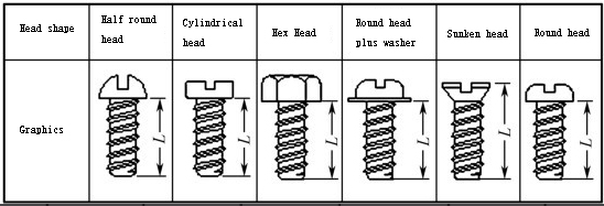
1 According to head type, it is divided into round head, countersunk head, round head with washer, hexagonal head, cylindrical head, semi-round head, semi-countersunk head, etc.

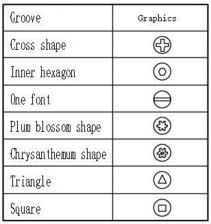
2 According to groove shape, it is divided into cross shape, inner hexagonal shape, straight shape, plum blossom shape, chrysanthemum shape, triangle, square, etc.
3 According to tooth tail type, it is divided into flat tail, pointed tail, flat tail opening, pointed tail opening, etc.
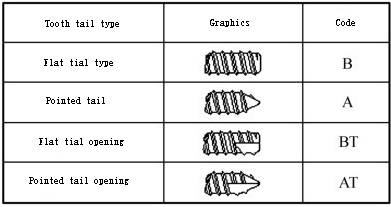
(4) Examples of naming of self-tapping screws.
① PB2.60mm*4.00mm is a self-tapping screw with a round head and flat tail of 2.60mm, and length is 4.00mm.
② PWB2.60mm*5.00mm is a self-tapping screw with a round head and a washer and a flat tail of 2.60mm, and length is 5.00mm.
③ PA2.60mm*6.00mm is a self-tapping screw with a round head and a pointed tail of 2.60mm, and length is 6.00mm.
④ KB2.60mm*5.50mm is a self-tapping screw with a countersunk head and flat tail of 2.60mm, and length is 5.50mm.
⑤ PAT2.60mm*7.00mm is a self-tapping screw with a round head and a pointed tail opening of 2.60mm, and length is 7.00mm.
Calculate length of self tapping screw
Difference between self tapping and machine screw
1. Appearance comparison
(1) Relatively speaking, self-tapping screws have a larger pitch and thicker tooth profile than machine screws.
(2) Tail type of machine screws has no pointed tail and no opening.
2.With or without nuts?
(1) Self-tapping screws do not require nuts due to their self-tapping properties, as long as there are holes.
(2) Machine thread screws require nuts or threaded holes matching screw thread type.
3. Application scope
(1) Self-tapping screws and machine screws are commonly used in plastics, thin or soft metal parts, wood products, etc.
(2) Machine screws are often used to connect metal parts. If used for other materials, nuts need to be embedded in advance.
4.Number of disassembly
(1) Self-tapping teeth should not be disassembled frequently, otherwise they will fail due to tooth slippage.
(2) Machine screws can be removed frequently.
Design of self-tapping screws and screw column
Self-tapping threads are often used in plastics, and plastic parts have self-tapping screw column dimensions.
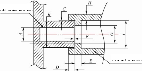
Size description:
Dimension A is inner diameter of self-tapping screw column.
Dimension B is outer diameter of self-tapping screw column.
Dimension C is limit gap between two screw columns.
Dimension D is limit height.
Dimension E is thickness of glue level supported by screw head.
Dimension F is Z-direction gap between two housing screw columns.
Dimension G is diameter of hole through which screw passes.
Dimension H is wall thickness of screw post of lock screw housing.
Dimension I is diameter of screw head hole, which is 0.20mm larger than diameter of screw head.
Depth of self-tapping screw column is not less than 2.50mm. The larger screw, the deeper depth will increase accordingly.
Commonly used lengths of self-tapping screws are 2.50mm, 3.00mm, 3.50mm, 4.00mm, 4.50mm, etc.
Unit: mm
| Size A | B | C | D | E | F | G | H | |
| Screw 1.40 | 1.10 | ≥Φ2.80 | 0.10 | ≥1.00 | ≥0.80 | 0.10 | Φ1.60 | ≥1.00 |
| 1.70 | Φ1.30 | ≥Φ3.20 | 0.10 | ≥1.00 | ≥0.80 | 0.10 | Φ1.90 | ≥1.00 |
| 2.00 | Φ1.60 | ≥Φ4.00 | 0.10 | ≥1.00 | ≥1.00 | 0.10 | Φ2.20 | ≥1.00 |
| 2.30 | Φ1.90 | ≥Φ4.50 | 0.10 | ≥1.00 | ≥1.00 | 0.10 | Φ2.50 | ≥1.00 |
| 2.60 | Φ2.20 | ≥Φ5.00 | 0.10 | ≥1.00 | ≥1.20 | 0.10 | Φ2.80 | ≥1.00 |
| 3.00 | Φ3.50 | ≥Φ5.50 | 0.10 | ≥1.00 | ≥1.50 | 0.10 | Φ3.20 | ≥1.00 |
| 3.50 | Φ3.00 | ≥Φ6.00 | 0.10 | ≥1.00 | ≥1.50 | 0.10 | Φ3.70 | ≥1.00 |
Tips: Above data are based on ABS plastic material. If it is a harder plastic, inner diameter of self-tapping screw column can be appropriately larger. If it is a softer plastic, inner diameter of self-tapping screw column can be appropriately smaller.
Self-tapping screw materials and common surface treatments
Commonly used materials for self-tapping screws include iron, low carbon steel, medium carbon steel, stainless steel, brass, etc. Commonly used surface treatments include nickel plating (silver white), zinc plating (blue zinc or white zinc, etc.), copper plating (red copper or brass, etc.), chrome plating (silver white or black), oxidation, black baking, etc.
Tips: Surface of stainless steel screws does not need to be treated and is mainly used for high-end products.
11 Dimensional accuracy of plastic parts
Accuracy of plastic products is not high. There are many reasons that affect accuracy of plastic products, such as type of plastic material, shape and size of plastic products, mold design and processing level, injection molding parameters, etc. State has promulgated tolerance standards for accuracy of plastic parts and divided them into accuracy levels.Unit: mm
| Basic size | Accuracy level | |||||||
| 1 | 2 | 3 | 4 | 5 | 6 | 7 | 8 | |
| Tolerance value | ||||||||
| -3 | 0.04 | 0.06 | 0.08 | 0.12 | 0.16 | 0.24 | 0.32 | 0.48 |
| 0.563-6 | 0.05 | 0.07 | 0.08 | 0.14 | 0.18 | 0.28 | 0.36 | 0.56 |
| 6-10 | 0.06 | 0.08 | 0.1 | 0.16 | 0.2 | 0.32 | 0.4 | 0.64 |
| 10-14 | 0.07 | 0.09 | 0.12 | 0.18 | 0.22 | 0.36 | 0.44 | 0.72 |
| 14-18 | 0.08 | 0.1 | 0.12 | 0.2 | 0.26 | 0.4 | 0.48 | 0.8 |
| 18-24 | 0.09 | 0.11 | 0.14 | 0.22 | 0.28 | 0.44 | 0.56 | 0.88 |
| 24-30 | 0.1 | 0.12 | 0.16 | 0.24 | 0.32 | 0.48 | 0.64 | 0.96 |
| 30-40 | 0.11 | 0.13 | 0.18 | 0.26 | 0.36 | 0.52 | 0.72 | 1 |
| 40-50 | 0.12 | 0.14 | 0.2 | 0.28 | 0.4 | 0.56 | 0.8 | 1.2 |
| 50-65 | 0.13 | 0.16 | 0.22 | 0.32 | 0.46 | 0.64 | 0.92 | 1.4 |
| 65-80 | 0.14 | 0.19 | 0.26 | 0.38 | 0.52 | 0.76 | 1 | 1.6 |
| 80-100 | 0.16 | 0.22 | 0.3 | 0.44 | 0.6 | 0.88 | 1.2 | 1.8 |
| 100--120 | 0.18 | 0.25 | 0.34 | 0.5 | 0.68 | 1 | 1.4 | 2 |
| 120-140 | 0.28 | 0.38 | 0.56 | 0.76 | 1.1 | 1.5 | 2.2 | |
| 140-160 | 0.31 | 0.42 | 0.62 | 0.84 | 1.2 | 1.7 | 2.4 | |
| 160-180 | 0.34 | 0.46 | 0.68 | 0.92 | 1.4 | 1.8 | 2.7 | |
| 180-200 | 0.37 | 0.5 | 0.74 | 1 | 1.5 | 2 | 3 | |
| 200-225 | 0.41 | 0.56 | 0.82 | 1.1 | 1.6 | 2.2 | 3.3 | |
| 225-250 | 0.45 | 0.62 | 0.9 | 1.2 | 1.8 | 2.4 | 3.6 | |
| 250-280 | 0.5 | 0.68 | 1 | 1.3 | 2 | 2.6 | 4 | |
| 280-315 | 0.55 | 0.74 | 1.1 | 1.4 | 2.2 | 2.8 | 4.4 | |
| 315-355 | 0.6 | 0.82 | 1.2 | 1.6 | 2.4 | 3.2 | 4.8 | |
| 355-400 | 0.65 | 0.9 | 1.3 | 1.8 | 2.6 | 3.6 | 5.2 | |
| 400-450 | 0.7 | 1 | 1.4 | 2 | 2.8 | 4 | 5.6 | |
| 450-500 | 0.8 | 1.1 | 1.6 | 2.2 | 3.2 | 4.4 | 6.4 | |
Tips: Tolerance standards are usually used as a reference. In actual work, actual assembly is generally used to test rationality of plastic products. To give a simple example, if plastic product produced meets national tolerance standards, but there is still an obvious gap when actual product is assembled, mold needs to be modified according to size of gap.
When marking tolerances on plastic products, important dimensional tolerances should be marked directly on dimensions, and non-important dimensional tolerances can be stated in a list.
For products with high precision requirements, the first-level tolerance in Table 4-5 should be used for important dimensions, and second-level tolerance should be used for non-important dimensions.
| Category | Material name | Recommended accuracy level | ||
| PS/ABS/PMMA/PC/polysulfone/polyphenylene ether/phenolic plastic powder/amino plastic powder/30% glass fiber reinforced plastic | High precision | Common accuracy | Low accuracy | |
| 1 | 2 | 3 | 4 | |
| 2 | PA6/PA66/PA610/PA9/PA1010/hard 3PVC/chlorinated polyether4 | 3 | 4 | 5 |
| 3 | POM/PP/HDPE | 4 | 5 | 6 |
| 4 | LDPE/soft PVC | 5 | 6 | 7 |
Table 4-6 Selection of precision grades of plastic products
Recommended
Related
- Motor Support Plate Die-Casting Process Design and Optimization07-29
- A Comprehensive Guide to Hot Runner Thermostats in Injection Molds: How Experts Choose, Use, and Rep07-29
- Hydraulic Cylinder Core Pulling Design Considerations07-28
- Interpreting Four Key Parameters of Injection Molding and Their Impact on Product Quality07-28
- Taking silicone oil fan clutch housing as an example, let's discuss analytical logic of leakage07-27