
(Medium Mold) Calculator Shell Injection Molding Mold Design
Time:2019-07-22 08:57:49 / Popularity: / Source:
In modern industrial production, mold has become an important part of national economy. Mold production has touched many fields such as electrical appliances, instrumentation, construction equipment, automobile industry, daily hardware, etc. It is a high-tech industry with high efficiency, high quality, low cost, low energy consumption and low pollution. It is also a technology that our country attaches great importance to. This design selects current popular electronic product - calculator, and designed mold determines plastic part as calculator case.
Product analysis
Calculator case product is shown in Figure 1. Plastic part is face of a Japanese brand calculator. Shape of product is a rectangular shallow shell. Two long rectangular holes from top are solar absorption screen, liquid crystal display, followed by 18 functions and function keys, and 15 numeric keys and arithmetic symbol keys in lower part. There are two small rectangular holes on top side of solar absorption screen, which require lateral core pulling.
Plastic part size is 125mm*66.5mm*5.60mm, plastic material is ABS, glue position thickness is 1.5mm. Plastic part weight is 9g.
Plastic part size is 125mm*66.5mm*5.60mm, plastic material is ABS, glue position thickness is 1.5mm. Plastic part weight is 9g.

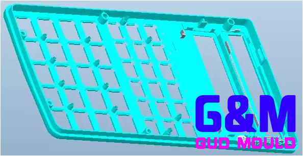
Figure 1 calculator shell product drawing
ABS resin is a terpolymer developed on the basis of modification of polystyrene resin. It is widely used in manufacture of enclosures for instrumentation, household appliances, telephones, televisions, money detectors and calculators. Fluidity of ABS is related to both injection temperature and injection pressure, with injection pressure being slightly more sensitive. For this reason, it is possible to reduce melt viscosity and improve mold filling performance from injection pressure during injection moulding process.
Injection molding mold design points
01. Mold alignment
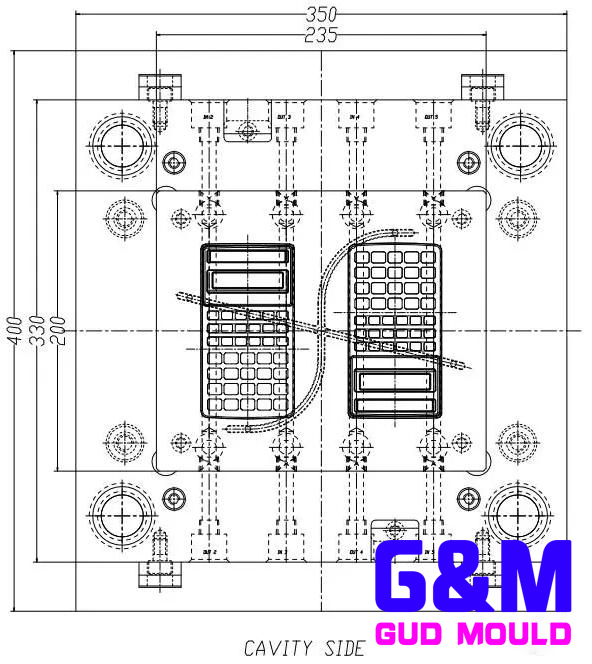
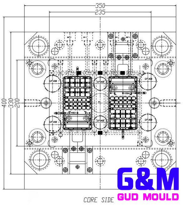
Electronic calculator belongs to office stationery electronic products produced in large quantities. Number of mold cavities is as much as possible. Combined with size and structure of plastic parts, number of cavities is determined to be 2. If design is 1 out of 4, mold is too large and requires a larger injection machine, and technical economy is not ideal. Mold base specification is LKM FCI3335 simplified sluice die. Injection molding mold design is shown in Figure 2.
02. Pouring system design
Electronic calculator case product is an appearance part, and product is relatively simple. Weight of product is only 9 grams, and wall thickness of plastic part is 1.5mm. Outer surface of plastic part cannot be designed with a gate. Therefore, mold structure of pin-point gate switching sub gate is designed. Determination of position and quantity of gate is result of summarizing experience of similar products before. As shown, two gates were designed. Reason why a gate is difficult to fill may be that there are many holes on the surface of plastic part, which affects flow of plastic.
03. Determination of shrinkage rate
Shrinkage rate of ABS plastic ranges from 4% to 7%. According to conventional practice, it is usually 5%. This set of calculator mold summarizes experience of similar products for several years and determines shrinkage rate is 4%. It has been proved by practice that such injection molding mold design can meet requirements. After upper and lower shells are assembled, art line is beautiful and hand feels not to be scratched. However, it should be noted that shrinkage of injection molding mold design of bottom shell matched with this shell is still 5%.
04. Core pulling mechanism
05. Core pulling mechanism
Two small square holes on the side of plastic part are designed with two small slider inserts S01, sharing a single slider seat. Due to small stroke, slider is opened by a spring, see injection molding mold design.
06. Mold open control component
Four nylon clasps are mounted on A plate, and top of nylon clasp is not drilled. Mold is opened with a screw and a pull plate to save space in mold.
07. Mold inserts
Rear mold core is made of large inserts to facilitate processing and polishing of spigot position, and column positions are all set with needles.
08. Water transport design
Front and rear molds are designed with cooling water channels to ensure effective cooling. Nozzle push plate is also designed with two water transports.
09. Die ejection system design
Use a thimble to eject. A thimble is designed near bone and column.
10. Exhaust system design
Inserts and thimbles, front molds are grounded accordingly.
Conclusion
Structure of electronic calculator mold is simple. The key is to sum up experience, summarize experience of doing similar products before and use it. From perspective of use effect since start of production, calculator mold has completely met requirements of mold style book. Can be used as a reference for similar mold designers.
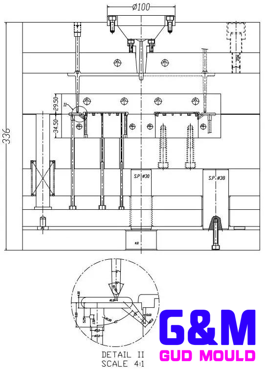
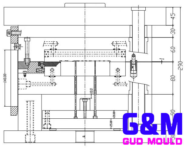
Figure 2 calculator shell injection molding mold design
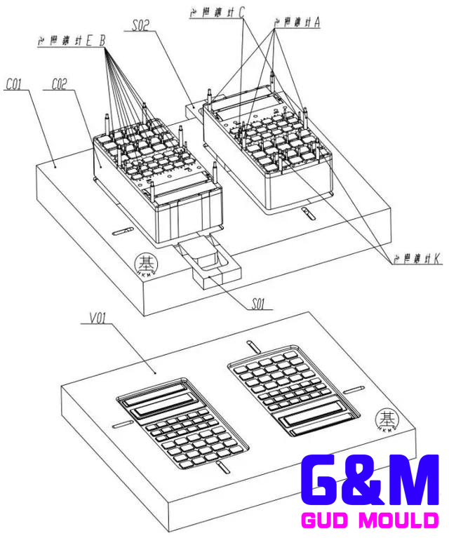
Figure 3 Calculator face shell mold explosion diagram
Recommended
Related
- A Comprehensive Guide to Hot Runner Thermostats in Injection Molds: How Experts Choose, Use, and Rep07-29
- Hydraulic Cylinder Core Pulling Design Considerations07-28
- Interpreting Four Key Parameters of Injection Molding and Their Impact on Product Quality07-28
- Taking silicone oil fan clutch housing as an example, let's discuss analytical logic of leakage07-27
- In-depth Study of Mold Gate Design07-27